

Technical · 6 min read
Drilling is one operation of four
A drilled hole is a location, not a finished bore. The distance between the two is where most mold base dimensional problems are born — and it is settled on the drawing, not at the machine.
Every hole on a mold base starts as a drill mark, and that is the only part a drill can promise. A twist drill is a long flexible tool pushed by two cutting edges that do not cut equally. As soon as it enters the steel it pulls itself toward the softer side, and the deeper it goes the more the error compounds: coolant cannot reach the tip reliably, the chip curls back against the wall, and a thin core wanders. The result is a hole that is very close to where you asked for it at the entry surface and progressively further off further in. That is normal behaviour for drilling, not a defect, and it is the reason the operation above the drill exists.
Four operations, each buying a different property. Drilling establishes position and removes the bulk of the material. Reaming follows an existing hole and brings the diameter to size with a good finish, but a reamer follows the hole it is given — it improves straightness only marginally and cannot move the axis. Boring rotates a single point on an adjustable head along the axis of the machine spindle, so it corrects position and straightness and can hold a size accurately, because the diameter can be measured and stepped in while the tool is still in the cut. Grinding finishes what boring has already brought to size. In practice most base work is drill and ream for medium holes, bore where the size range is awkward or the position matters, and grind where the hole has to be a sliding or rotating fit.
Depth against diameter is the cut-off. Hole depth is always quoted against its own diameter, because a 10 mm drill at 40 mm deep and a 30 mm drill at 40 mm deep are not the same job: the first is 4×D and ordinary, the second is barely over 1×D and trivial. Once a hole runs past roughly 4–5×D, chip evacuation and coolant delivery at the tip become the limiting factor and the drill starts to walk; that is the band where through-tool coolant, a pilot hole or a dedicated deep-hole operation starts to earn its place. It is also why a water line crossing a thick plate is planned a little differently from a guide bore in the same plate: same hole diameter, very different length-to-diameter ratio, and a lower accuracy expectation on the water line.
A drilled hole carries two tolerances at once, and they behave differently. Position is set by the machine and the setup, so a drilled hole is usually where you wanted it. Diameter and straightness are set by the tool and the depth, and they are where the variation shows up. The mistake on the drawing is asking for one tolerance to cover both, or asking for a diameter so tight that only boring or grinding can achieve it — on a feature that no one needed to be that accurate.
On this site the two tolerance classes are already decided. Guide-pillar and guide-bush bores and all fitting or ground faces are held to ±0.02 mm; dimensions that are not a fit are held to 0.3 mm; ground faces finish to Ra 0.8 µm, and anything over 600 mm is agreed case by case. Applied to hole-making, that means the plate datum, the bore positions and the bores themselves are fitting features and get the tight band, while a clearance or vent hole — whose only job is to let air, water or a fastener through — is a general-tolerance feature. Marking a clearance hole as a fitting feature does not make the tool any better. It changes how the job is planned, what it is inspected against, and what it costs. The tolerance note covers the classes in full.
The bore positions are what a buyer is really buying. Get the diameter slightly wrong and it can usually be reamed one step up or bushed back. Put a guide bore in the wrong place and the plates no longer line up — the pillars bind on closing, the shut-off faces stop meeting evenly, and the whole stack has to be reworked or remade. There is no allowance for that error, which is why the bores are machined in a single setup on one machine rather than being carried between operations: bore each plate separately and you have introduced a setup error between the two plates for no gain. The guide system note takes this further, and it is the one paragraph in this article worth reading twice.
The operations you cannot see in the price. Tool changes, spot checks, and re-clamping the plate. The small quality-related stops in the job — a reamed bore checked with a plug gauge or an air gauge before the next one is cut, a ground finish measured rather than assumed — do not appear in a supplied drawing and do not appear on a delivery note. They are the reason two suppliers can quote different prices for what looks like the same plate. Before accepting a saving, ask which operation was removed: if it was the one that reamed, bored or ground the bore, the price dropped for a reason you will find in the press.
What goes on the drawing. Bore diameter and the tolerance class, or the fit and the mating component; position from a common datum — not chained hole to hole; whether each bore is through, blind or stepped, and for a blind bore the usable depth as well as the drill point depth; finish on the bores that take a sliding or rotating part; and which bores are fits and which are clearance. If a pillar or bush is being supplied to fit, quote the component drawing as well, so the bore can be worked to the component rather than to a nominal. The RFQ checklist lists the rest of the pack.
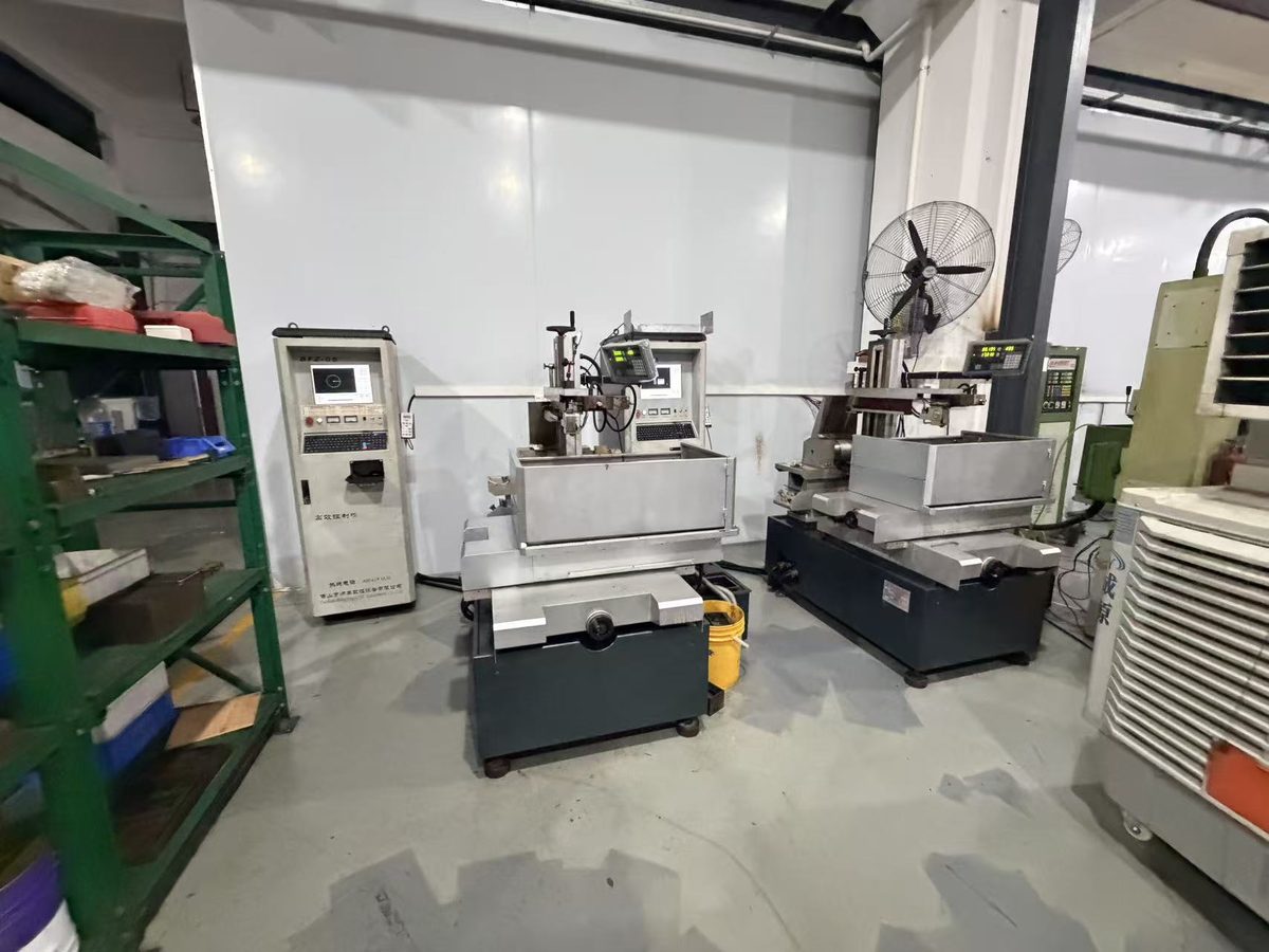
Where this sits in the week. Hole-making runs inside the normal sequence, so most bases ship in seven days from order confirmation, at 2,000+ sets a month, with a minimum of one set. The bores are our own work — drilled, reamed and bored in-house on the machines listed on the factory page — and every base is inspected before dispatch with the records travelling with the shipment. Send the drawing and the mating component callouts with it, and we will tell you which bores get which operation and where the tolerance belongs.
Read the drawing the way the machine reads it. One tolerance note intended to cover every hole on the plate is the most common cause of an expensive base and a late delivery, and it is entirely avoidable. Decide which holes have to be accurate, move the rest into the general band, and the base gets cheaper, faster and easier to inspect — the rare change that improves all three at once. If you are unsure which features need the tight callout, send the mating parts with the drawing and let the non-standard quotation show what each feature costs.
Related