

Ejection · 5 min read
Ejector pin holes: the holes in a mold base that get decided last
Ejection is settled on the drawing, not on the press. Here is what the base has to get right before a pin ever moves.
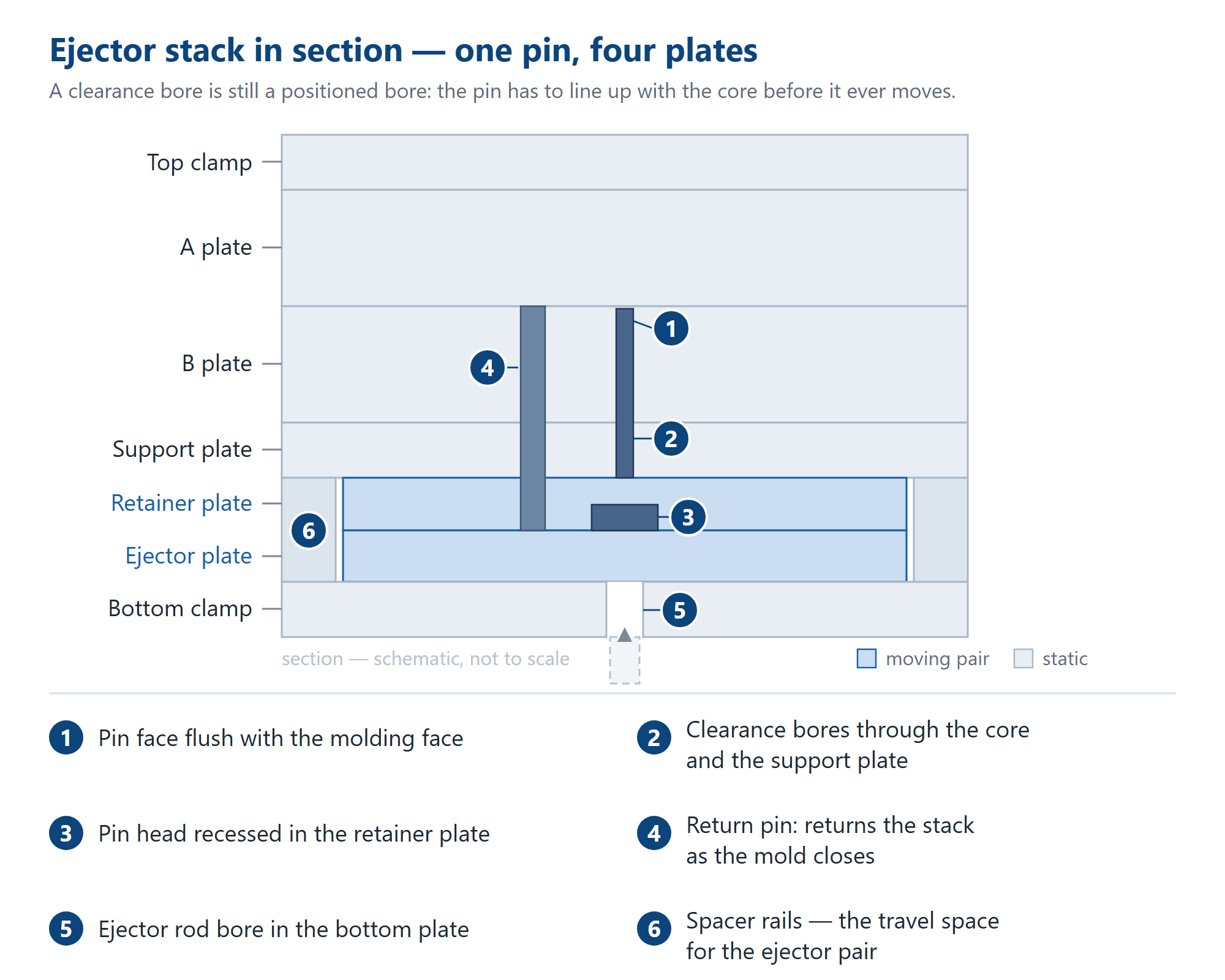
Ejector pins touch the part on every cycle, and they are usually the last thing anybody specifies. A base drawing normally arrives with plate sizes, a pocket layout and four or five tolerance callouts; the ejector pattern comes later, or as the words “as per your standard”. That order is expensive, because every decision about ejection is a drawing note before the first cut and a new setup, a new inspection and a new date after it.
The arrangement comes first, because everything else follows from it. The ejector plates are a pair that floats between the support plate and the bottom clamping plate, a space created by spacer rails along the two sides whose height is what the pair travels in. The upper plate holds the pins by their heads; the lower plate is what the machine pushes. The knock-out bore in the bottom plate lets that push through, and the complete A/B assembly is where the ejector pattern, the runner and the parting line have to agree.
The pin passes through four plates, and the bores it meets do three different jobs. In the retainer plate the pin is held: the head sits in a recess cut into that plate. In the core plate and the support plate it passes through clearance bores that are not meant to touch it. In the core insert, where the pin reaches the molding face, the bore is a working fit — the surface the pin slides against, cycle after cycle. Three jobs, three requirements, one axis.
A clearance bore is not a hole you can put anywhere. Only one of the three is a fit, so only one is toleranced, and the other two get treated as if nothing about them mattered. Size is not the problem — a clearance bore sits comfortably inside the general non-fitting tolerance of 0.3 mm. Position is. Put the support plate's bore half a millimetre off the core's bore and the pin is no longer sliding, it is being bent, very slightly, thousands of times. So the callout worth making is a position, not a size: if the drawing carries an ejector layout, send the coordinates of every pin. The tolerance note covers the rest.
The head recess is a dimension the base owns. The head is trapped between the retainer plate above it and the ejector plate below, so the two ejector plates have to close flat with the heads inside. Cut it short and they cannot close: the assembly becomes thicker than the space it lives in. Cut it deep and the head sits low — harmless, until you remember that the working length of every pin is measured from the face its head bears on. A recess a fraction too deep is a set-wide error. Treat the recess as the fitting dimension it is.
The recess also has to line up with the pin hole above it, which is why the plates carrying the two are worked together: bore them stacked in one setup, or bore the base and transfer the position from it. Drill each plate separately from coordinates, on different days, and the errors add instead of cancelling. None of that shows up at goods-in, which measures plates one at a time — it shows up at assembly, when the pin goes in hard or drops in loose. Drilling alone does not deliver a bore you can trust for position; the hole-making note explains why.
The return side is a stack dimension. Return pins push the ejector assembly back as the mold closes, and their length is built from the plates around them: ejector plate, retainer plate, support plate, core plate. Change one of those thicknesses and you have changed every return pin in the set, which is the practical reason to freeze plate thicknesses before the base is machined. “Make the support plate 10 mm thicker for stiffness” is a reasonable request at quotation stage and a re-order of every return pin afterwards. Too short, and the ejector plates are not fully returned when the mold closes, leaving the pins proud of the core to be crushed. Too long, and they interfere earlier than the design intended.
The pair needs its own guiding. Ejector guide pins and bushes are usually separate from the mold's main guide system, because their job is to keep the two ejector plates square as they travel, not to align the halves of the mold — a different set of holes with a different job, as the guide system note makes clear. If your base and your components come from different suppliers, check which of the two is sending them; it is a small line item to duplicate and an annoying one to be missing on assembly day.
Symptoms are worth learning: ejection failures rarely announce themselves as ejection failures. A witness mark in the same place on every part means one pin standing proud of the molding face. A part that hangs on one corner and then releases points at pin positions rather than pin lengths. Pins that gall in the retainer plate are usually about fit, not lubrication: a bore that is too tight, with the clearance bores off-axis below it, loads the pin sideways on every stroke. A pin that breaks at the shoulder after a few thousand cycles is bending fatigue — look at the axis of the bores it passes through. Marks that appear after ten thousand shots but not after a hundred mean a pin bent a very small amount since the first stroke. Every one of those points back at a decision made before the plates were machined.
What to put in the base order: whether the base is supplied drilled for ejection or whether you will drill it; pin diameters with a position for each pin, taken from the part rather than a catalogue default; which plates get clearance bores and which one carries the fit; the head recess, how deep and in which of the two ejector plates; return pins, with a length or a stroke; ejector guide pins and bushes, and the same question for the main guide system; the knock-out bore in the bottom plate, with its size and position or a note that you do not want it; and the stroke, so the travel space can be checked against it.
None of this is difficult; it is just early. Every item above is a note on a drawing before machining and a re-setup, a re-inspection and a new date after it. The reason a base can ship in seven days is not that we machine quickly — it is that nothing is decided at the machine. With 2,000+ sets a month leaving our own floor, where the plates are cut, bored, ground and inspected under one roof, the notes you send are executed by the people who read them: no handover to lose them in, and no middleman between your tolerance class and the spindle.
A mold base is bought for its tolerances and remembered for its ejection. Put the ejector layout on the first drawing you send, not the last one.
Related