

Machining · 6 min read
Clamped flat, released warped: why the setup decides a mold base tolerance
Two decisions are made before the first cut and neither of them appears on the drawing: which face the plate is held by, and which face the numbers are measured from. Between them they decide whether the ±0.02 mm you specified survives the trip to your bench.
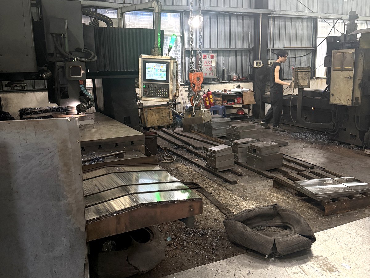
A mold base drawing is a set of claims about surfaces, and a surface only means something relative to another one. Before a pocket or a bore is cut, the person setting the job up chooses a face to hold the plate by and a face to measure from. Both choices are invisible in a quotation. Get them wrong and the part can be in tolerance on the machine and out of it on your surface plate — with nothing in the paperwork to explain the gap.
A plate is not rigid because it is heavy. Step clamps pull it down at four or six points, and between those points the plate is a beam, even when it takes a crane to lift. Sitting on an uneven surface, or clamped unevenly, the fixture pulls the plate into shape. The machine then cuts a top face parallel to the table, exactly as instructed, through a plate that is being held bent. The cut is correct. The error appears when the clamps come off: released, the plate returns to its own shape and takes the machined face with it — flat on the machine, out of parallel on the bench, nobody at fault in the record.
What a good setup does about it is unglamorous. Support goes under the clamp points rather than between them, so each clamp pushes against steel and not air — adjustable supports set to touch under each clamp. Clamping is even and in sequence, not one bolt until it stops. Where flatness really matters, the plate is roughed, released, allowed to sit, then clamped again lightly for the finishing pass, so the last cut is taken as close to the free state as a fixture allows. That is the honest reason a base with a tight parallelism callout takes longer: more setups, not better machines — the same separation of roughing and finishing that large plates are planned around.
The second decision is the datum, and that one you can control from the drawing. A drawing nominates faces — A, B, C — and dimensions run from them. The machine has its own zero, and the two are the same only because somebody made them the same. The trap is the raw stock face: convenient to probe, present on every plate, and square to nothing. Zero on a rolled face means every feature afterwards is measured from a surface that is about to be cut away.
So the first operation is not a pocket, it is a reference. Face one side, machine two adjacent edges square to it, and mark them. Those three faces carry the datum for everything that follows, and the marking is what lets them be found again after the plate has been off the table. It is also why a plate that comes back for rework cannot simply be re-cut: once its reference faces have been machined away, it has to be squared again before any dimension taken from them means anything.
Turning the plate over is where setups are won or lost. There are three ways back to the same zero and they cost different things. Edge stops against the squared edges are quick, and only as good as those edges. A dowel pin in a spare hole locates positively and leaves a witness hole you may not want. Indicating an already-machined face is the most accurate and the slowest, and it needs a machined face to touch. A drawing that offers none of the three is asking for a setup measured by eye.
Grinding runs on the same physics with a magnet instead of clamps. A surface grinder holds the plate down magnetically, which pulls it flat against the chuck, and grinds it flat in that condition. Release the magnet and a part carrying any built-in stress goes back to the shape it had. That is one reason grinding follows machining rather than replacing it, and why a plate that is thin against its area is the hardest job on the machine: the chuck can flatten it, the magnet cannot keep it flat.
Which brings the question that settles most arguments: measured clamped, or free? A parallelism figure taken with the part still bolted to the table describes the fixture. The same figure taken on a surface plate on three points describes the part — and that is the one your incoming inspection will reproduce. When two parties disagree about a base that is “out”, the measurement condition is more often the difference than the machining. Agree it in writing before the order: free state, on a surface plate, from the datum faces marked on the drawing.
What we hold is stated the same way on every base: fitting and ground faces parallel and square to ±0.02 mm, guide-pillar and guide-bush bores positioned to ±0.02 mm, ground faces at Ra 0.8 µm, non-fitting dimensions at 0.3 mm, and anything above 600 mm agreed before the quotation goes out. Critical features are measured on a CMM before the base is packed, and the record travels with the shipment — which is what an inspection record is worth once the conditions can be repeated at your end.
Four things the drawing can add. Mark the datum faces, and say if the assembly is measured from a bore rather than an edge. Say which face carries the parallelism callout — on a stack it is usually the parting-line face, and machining both faces flat is not the same as making them parallel to each other. Say whether the plate gets machined again at your end: if a pocket or a shut-off is cut later, that face needs stock left on it. And say how you will inspect, including whether you measure the base bolted to something that is not flat.
Five questions worth asking any supplier, because the answers describe a process rather than a promise. How many setups does this base need? Which faces are your datum, and are they marked? Is the part measured free or clamped? What happens if a plate moves after roughing? Can I see the flatness record for the faces I care about? A shop that machines its own plates answers each of those in a sentence. A shop that passes the drawing on answers with the delivery date.
None of this is exotic work. It is the ordinary discipline of knowing which face you hold and which you measure from, settled before the first cut or not at all — the same reason a second base dimensioned from a different edge matches the first on paper and will not go into the press. On the custom and non-standard bases we machine to drawing, it is the same discipline that puts standard work on the truck in seven days from order confirmation, across more than 2,000 sets and pieces a month on our own machines, with no middleman between the drawing you send and the person who clamps the plate to the table. Send a drawing with the datum marked and the reply will say what we will hold and how we will show it.
Related