

Workshop · 6 min read
Dowels locate, screws clamp: the holes that hold a mold base together
A base comes apart for maintenance many times in its life. The screws pull it together; the dowels are what put it back in the same place. Most of what goes wrong in these holes is decided at the drawing stage, long before anyone cuts metal.
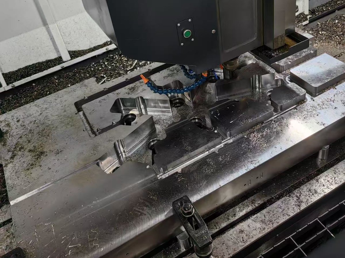
A finished mold base leaves the shop with a lot of holes in it, and at a glance they look alike. They are not. Two families decide whether the base still lines up after its third teardown: the holes with a thread, which pull plates together, and the holes without one, which hold a ground pin and decide where the plates sit. The first family carries load. The second carries position, and it is the one that gets specified loosely.
The difference is clearance. A screw sits in a tapped hole with play in the flanks of the thread, so the two plates can move before the screw is tight, and they settle somewhere slightly different each time the joint is closed. A dowel does the opposite: a reamed hole and a ground pin in an interference fit put the plate back in one place, every time. That is why an interface designed to be stripped for maintenance is dowelled, and an interface that is only ever assembled once often is not.
The two are paid for differently, which is worth separating before a price is agreed. A tapped hole is drilled and tapped in one setup, seconds each, and its cost lives in the number of holes and how well the tool reaches them. A dowel hole is drilled and then reamed, and it has to sit in position from a datum the other plate agrees with: a second operation, on a machine that can hold the position. A drawing that marks two plates as dowelled is asking for that operation, and a quote that ignores it is pricing a different base. The operations that get a hole to that position are set out in Drilling is one operation of four.
“M10” is not a callout. An M10 coarse thread runs at 1.5 mm pitch; an M10 fine is 1.25 or 1.0. An inch drawing may mean 3/8-16 UNC or 3/8-24 UNF, neither of which is interchangeable with anything metric. A coarse screw started into a fine hole turns a thread and a half and stops; the next instinct is to force it, and the thread is gone. Mixed sourcing makes that the normal case rather than the exception: a European drawing, standard components from Japan, fasteners bought locally. Write the series, the size, the pitch where it is fine, and the depth.
A blind tapped hole carries two depths, and only one of them usually gets written down. The thread has to be deep enough for the screw to develop its load — in steel, roughly one to one and a half times the diameter is the usual figure, and past that the screw breaks before the thread strips. The drill has to go deeper than the thread, because the tap needs room to run out and the chips need somewhere to go. Specify the thread depth on every tapped hole, and the drill depth wherever the plate is thin enough that breaking through would reach a pocket or a water line behind it.
A screw joint needs three things to work: a clearance hole through the plate on top, a tapped hole in the plate below, and a flat seat for the head. The seat is the one that gets forgotten. A counterbore cut too shallow leaves the head standing proud; cut too deep, it takes material out of a plate that may not have much to spare. On a milled face the head lands on the high spots, the screw feels tight, and the plates are still apart. Spot-facing is a separate operation, and it deserves its own line on the drawing.
Blind holes fail quietly. A tapped hole with chips at the bottom takes a screw that feels tight and is not: the screw has bottomed on debris, the joint has not closed, and the stack height is now wrong by the depth of the chips. A dowel driven into an unvented blind hole compresses the air beneath it and sits high — the pin looks seated and the plates are not. Both are caught by cleaning each hole and checking its depth with a pin before assembly — cheap, and the first thing dropped when a job runs late.
A dowel hole is reamed, not drilled, and its position is a fitting dimension rather than a clearance one. The pin should reach into each plate by at least its own diameter; a pin that enters the second plate by a few millimetres locates nothing and will wallow its hole. Whether the pins are fitted here or shipped loose is a real choice: fitted pins speed assembly at the customer's site, loose pins let the toolmaker set final position once the cavity is in. The guide bores follow the same logic — guide pillars and bushes only line up if their bores were positioned as fitting features.
A dowel that has sat in a plate for two years does not come out with a drift. Two details decide how that goes: whether there is a way to extract it — a tapped hole in the pin end, or a through hole to drive it from behind — and whether it was greased on assembly. Steel on steel rusts together, and a pin hammered out at an angle bells the mouth of the hole, after which the hole no longer locates anything. Extraction features cost almost nothing at the drawing stage and cannot be added later.
What the drawing should settle, then: which interfaces are dowelled and how many pins go in each; the pin diameter, and whether the pins come fitted or loose; the thread series, class and depth on every tapped hole, with drill depth for the blind ones; which holes are fitting features and which are clearance; whether the base ships assembled or knocked down; and whether tapped holes are plugged for transport. Together that is the difference between a base that goes back together and one that has to be re-aligned by hand.
The symptoms are consistent enough to read backwards. A stack that needs re-aligning after every strip. Screws that want re-torquing after a few cycles. A screw that bottoms out before the joint closes. A thread that strips well below the torque its size should take. A dowel hole gone oval. Mismatch or flash that appears after a maintenance stop when the first trial was clean. None of these is a machining defect in the ordinary sense; each is a decision about a hole taken at the drawing stage, months earlier.
Locate first, clamp second is the whole of it, and it is the ordinary output of a shop that cuts its own plates. Work leaves the floor as custom and non-standard mold bases or, where a catalogue size already fits, as a standard mold base. The seven-day figure covers standard sizes and plain jobs, with complex work quoted a firm date before cutting starts; over 2,000 sets and pieces a month pass through our own machines; and there is no middleman between the drawing you approve and the machine that cuts it.
Related