

Technical · 6 min read
Where the base meets the press: five interfaces decided on the drawing
A mold base can be square, flat, on size, bored to position and still never run. The machine only cares about five features, and all five are settled before the plate is cut.
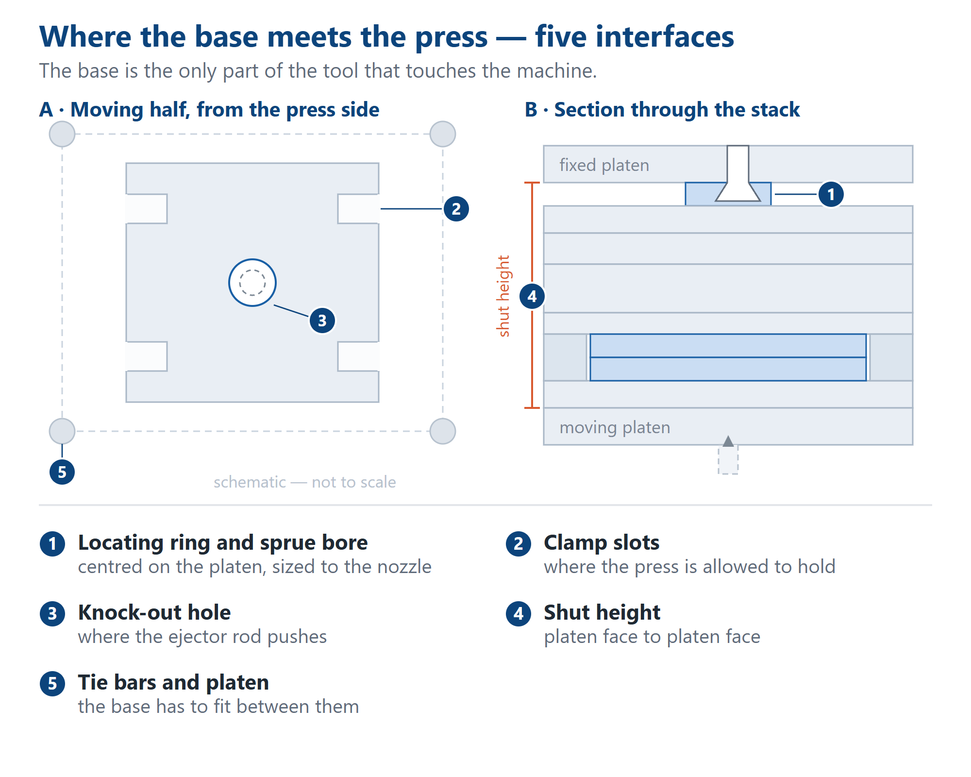
Every other dimension on a mold base is judged by the part it makes. These five are judged by a machine: tie bars, a platen, a locating recess and an ejector rod, none of which care how well the pockets were cut. Get one of them wrong and the base goes back on the pallet — not because it was machined badly, but because nobody carried the press data as far as the drawing.
The locating ring is a fit, not a detail. On the fixed half the ring enters the recess in the platen and centres the whole stack on the nozzle. Two numbers do the work: the ring’s outside diameter against the recess diameter, and how far the ring stands proud. A ring that is small sits loose in the recess and the stack can shift under injection pressure, which shows up as an offset sprue and flash around the sprue bush. A ring that stands too tall bottoms in the recess before the clamp faces meet, and the tool will not seat flat however hard the clamps pull. Ask for the recess diameter and depth with the order, not after the tool is on the crane.
The sprue bore and its radius belong to the nozzle. The bore carries the sprue bush; the radius at its mouth has to match the nozzle tip. Too small and the tip stands off, the joint leaks, and a ring of flash appears around the sprue that somebody picks out by hand every cycle. Too large and the tip is unsupported, so material cools in a step at the joint and pulls a string when the mold opens. That dimension is written on the molding machine, not on the mold drawing — which is exactly why it goes missing.
Clamp slots: leave somewhere to hold it. A press holds a mold base at the edges of its clamp plates, through slots, or with magnetic chucks, and every one of those methods needs clean, flat, accessible material at a known position. A plate used corner to corner — pockets, a water manifold, a slide seat, a hydraulic cylinder — can leave nothing at the clamping line. On large bases the clamp slots are often machined into the plate rather than left to the customer, and then they have to be on the drawing: clamp method, clamp positions against the platen’s T-slot spacing, and whether the base is held on its outside edges or through slots.
The knock-out hole is the machine’s position, not yours. The ejector rod rises through the moving platen at a fixed point, and the hole in the bottom clamp plate has to be there and has to clear the rod. Offset it and the rod pushes the ejector plate off-centre: one side of the plate leads, the pins gall, and the part lifts unevenly. Make it tight and the rod peens the edge of the hole — a repair on a plate that is already assembled. This hole is not the same family as the ejector pin bores; those are positioned by the part, this one by the press. Send rod diameter, its distance from the platen centre, and whether the machine pushes with one rod or several.
Shut height is a sum, not a choice. Between the fixed clamp plate face and the bottom clamp plate face sits every plate in the stack, and the total has to land inside the press’s daylight. It is the number that moves silently: add a support plate, add a spacer for more ejection travel, change a plate thickness to suit a deeper pocket, and the shut height has changed with it. If the base is short, the tool needs a spacer — which is a second change, because a spacer also changes how far the ejector plate can travel. If it is tall, it does not close at all. The stack belongs on the drawing as a total, not only plate by plate.
Tie bars and platen footprint. The base has to pass between the tie bars and land on the platen. A base a few millimetres wider than the gap cannot be loaded at all, and no amount of machining recovers it — that is a new base. The platen can also be smaller than the base, in which case part of a clamp plate hangs unsupported and the clamps end up where the T-slots are not. Run this check first, because it is the only one with no repair.
The two documents rarely meet. The mold designer draws to the part; the press data lives in a manual or on a plate bolted to the machine. The buyer is usually the only person holding both, and the gap between them is where these five features get guessed. A base machined to a drawing that says nothing about the press is not badly made. It is unfinished, and the finishing happens at the customer’s bench with a drill and a grinder.
What to send, and where it ends up. A press data sheet is short: machine model, platen drawing with T-slot spacing, locating ring recess diameter and depth, nozzle radius, ejector rod diameter and position, clamp method, daylight range. On our side those numbers become a press-interface note on the drawing and are checked at quotation, before steel is allocated. One page, and the five most expensive questions in the order stop being questions.
Symptoms, and the interface behind them. A part sticking on one side is a knock-out position. Flash ringing the sprue is the ring fit or the sprue radius. A mold that shifts under pressure is clamping. A tool that will not close is shut height. A base that will not go in is footprint. None of these reads as a mold base defect on the shop floor, which is how a base gets blamed for a press that was never described.
Six lines for the RFQ. Press model. Platen drawing or T-slot spacing. Ring recess diameter and depth, with the nozzle radius. Ejector rod diameter and position. Clamp method and clamp positions. Target shut height with the daylight range. Six lines, and the quotation covers the interface instead of only the steel.
On our floor a base leaves with the stack inspected, the bores measured and the record in the crate, usually in 7–10 days, off a floor that turns out more than 2,000 sets and pieces a month, with no middleman between your drawing and the machine that cuts it. Whether it is a standard size or a base cut to your own plate list, the five interfaces are settled on the drawing — so put the press data on it and let the machine be the last thing that surprises you.
Related