

Product / case · 6 min read
When the parting line is not flat: buying a complex surface mold base
A flat parting face can be measured with a straightedge. A curved one needs a model, a datum and a decision about which band actually seals. That decision is where useful machining starts.
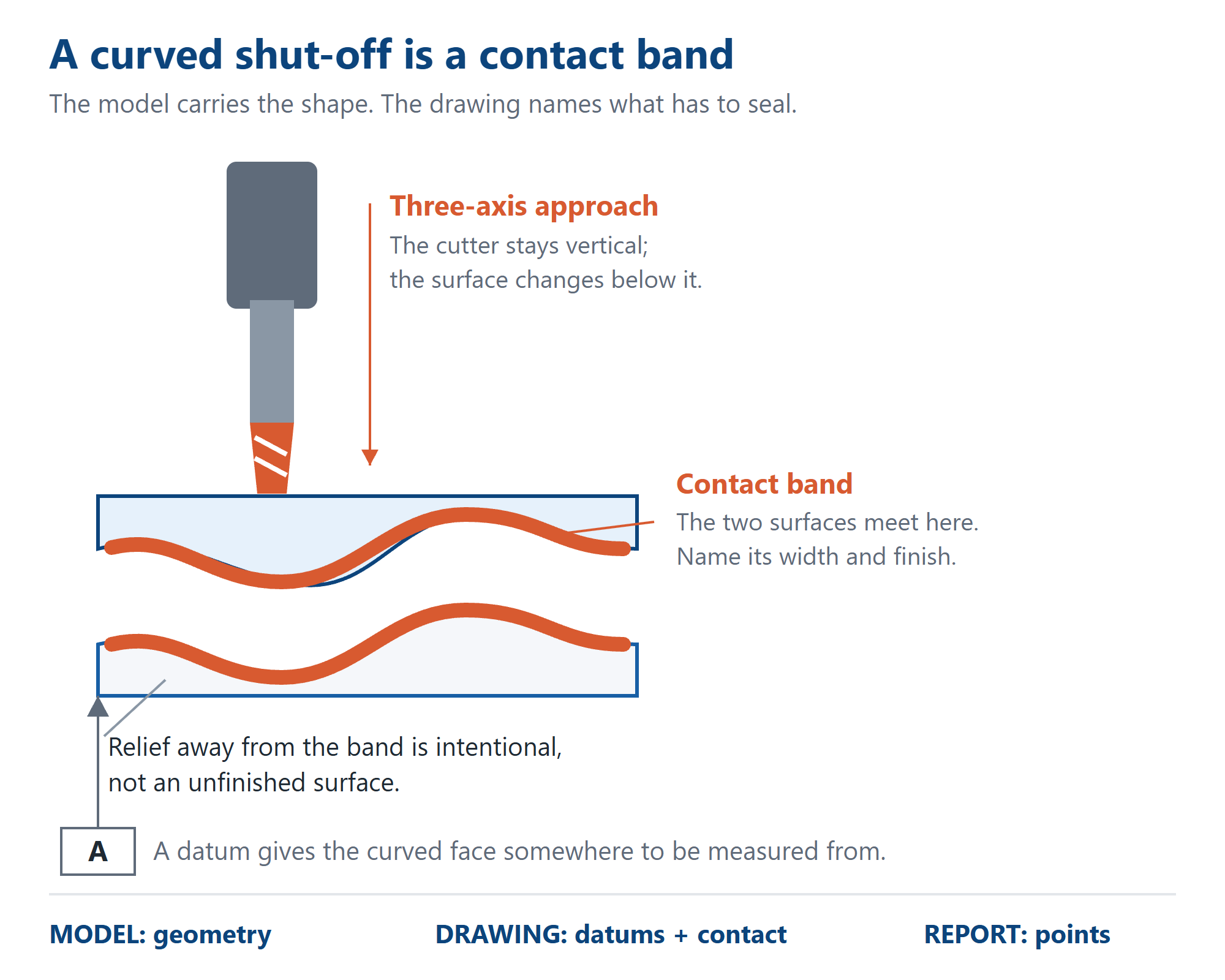
On a conventional base, the two halves meet on one plane. On a part with a step, a curved edge or a shaped shut-off, they meet on a surface that changes height as it crosses the plate. The model can make that surface look effortless. The machine still has to reach it, the two sides still have to meet, and somebody still has to inspect the result. A complex surface mold base is therefore not a standard base with a more elaborate pocket. It is a different description of contact.
The whole sculpted surface does not have to seal. The working feature is usually a contact band around the cavity or along a shut-off. Away from that band, the design may deliberately relieve the surface so that only the useful area has to be finished and matched. If the model does not distinguish the two, the shop faces an unattractive choice: finish every visible face as though it were functional, or decide on the buyer's behalf where contact matters. Both are avoidable. Mark the contact band and the relief on the drawing.
That band has a width as well as a shape. Too little of it and the load is concentrated on a narrow edge; too much and the job becomes a large matched surface that adds finishing and inspection without improving the seal. We are not going to put a universal width on it here, because the right figure follows the part, the insert and the load. What the buyer can do is name the boundary. A coloured model face with no dimension is a hint; a bounded band on the drawing is an instruction.
Three-axis machining fixes the direction of approach. The spindle remains vertical while the cutter follows the changing surface. That is well suited to many swept faces and stepped shut-offs, but it cannot reach underneath an overhang or approach a wall from the side simply because the model shows that shape. The question to ask is not whether a surface looks smooth on screen. It is whether a cutter can see every part of it from the available setups. Where it cannot, the design needs a different split, another operation, or a change — not a promise made at quotation.
Cutter shape leaves evidence as well. A ball nose can follow a sculptured face, but its contact point and effective cutting speed change as the surface tilts. A flat or bull-nose cutter behaves differently on a floor and a wall. But a small internal radius, an abrupt change of slope and a deep narrow valley are manufacturing decisions. The corner-radius and tool-reach note covers the same constraint on ordinary pockets.
Roughing and finishing still need to be separated. A complex surface cut out of a stressed plate can move after the bulk metal is gone, just as a deep rectangular pocket can. Leaving stock for a later finishing pass gives the shop somewhere to correct that movement; asking for the finished surface in one aggressive cut takes the option away. The useful buyer question is therefore about sequence: what is roughed, what is left for finishing, and which face re-establishes the datum between them. The mechanism is the same one described in deep pockets and high cores, even though the final shape is different.
The 3D model owns geometry that a 2D sheet cannot practicably dimension. It should not own everything else by default. The drawing still needs to name the datum faces, the revision, the steel and delivery condition, the contact band, any permitted cutter witness, and which file governs if the model and PDF disagree. A shape can be mathematically complete and commercially incomplete. This is the same file-precedence problem as a drawing revision, with more places for an unstated assumption to hide.
A freeform face also needs a reproducible inspection plan. A single height at its highest point does not describe it, and a general note saying “profile to drawing” gives nobody a point to measure. Agree named sections or coordinate points taken from the drawing datums, including points on the actual contact band rather than on an easy horizontal surface nearby. The report should let your toolmaker see where any departure lies. Our ordinary inspection discipline still applies: critical features are checked before dispatch and the record travels with the shipment, but a useful record begins with points that mean something.
Finish is another boundary worth writing down. Machining a curved shut-off to its geometric position is not the same as polishing it for appearance, preparing it for texture, or matching it with an insert already finished elsewhere. Those are different scopes and different acceptance tests. If the final blueing or fitting happens in your toolroom, say so and specify the stock to be left. If the base is expected to arrive ready to close, name the parts it must close against. “Machine complete” does not answer either question.
That leads to the most important case decision: is the curved surface in the frame, in a replaceable insert, or across both? A frame-only order is clean when the mating insert is already dimensionally stable and its model belongs to the same revision. A combined frame and insert job lets one shop manage the contact directly, but the commercial boundary has to say where the base ends. The frame-and-insert interface is worth settling before the model is released, not after two suppliers have cut complementary mistakes.
For buyers sourcing from China, distance makes the file package more important rather than less. A Chinese mold base supplier cannot resolve an unmarked contact band by walking the part over to your mould designer. Send the native or neutral 3D model, the PDF that governs it, the insert envelope, the datum scheme, the contact and relief map, the finish split and the inspection points in one controlled package. That is a narrower and more useful version of what buying a mold base from China involves: the shape can travel instantly, but only if the decisions travel with it.
A practical enquiry can now be short. Send the model and its revision. Identify the press side and the datum faces. Mark where the tool seals, where it is relieved and where your own shop will finish. Say whether inserts are supplied, machined by us, or merely represented by an envelope. Ask for the proposed setups and inspection points before cutting. Those answers tell you more than a photograph of a complicated part, because they reveal how the supplier intends to turn the surface into a tool that closes.
This is work we quote from the model rather than from a cavity count, with the machining boundary agreed before a plate is committed. Ordinary bases usually leave our Dongguan, China shop in 7–10 days; complex work receives a firm date against the actual geometry. The plant machines more than 2,000 sets and pieces a month, and you deal directly with the factory that cuts the plates. Send the model with the contact band marked, and the first useful reply can be about access, finish and inspection instead of another request for the missing drawing.
Related