

Machining · 6 min read
Corner radii, depth and reach: what the cutter decides in a mold base
A drawing describes a shape. The tooling decides whether that shape can be milled at all — and a called-out inside radius is a decision about money, not a line to be drawn.
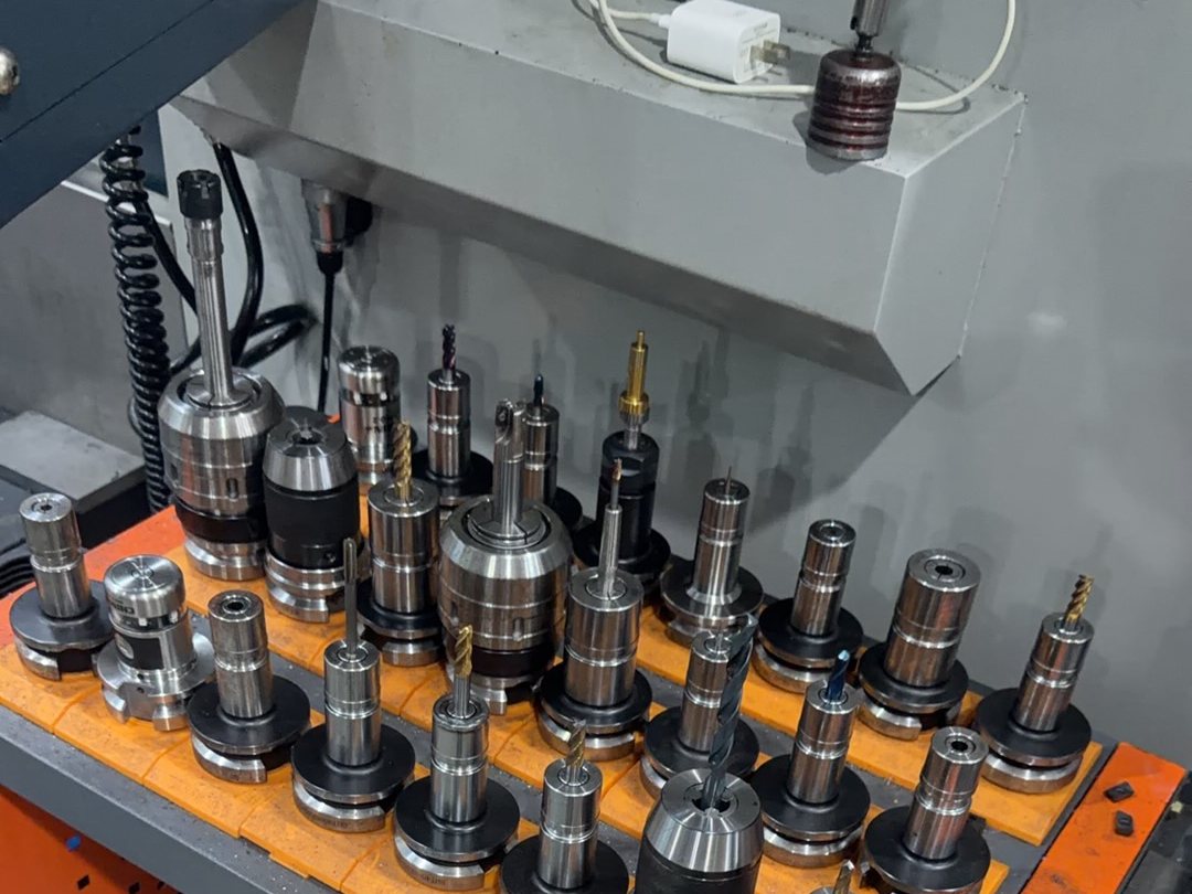
A mold base drawing is a description of a shape. It says nothing about how that shape will be produced, and that is where most of the cost sits. Every pocket, every wall and every bore is created by a cutting tool of a particular size and stiffness, held in a particular holder, presented to the work by a particular machine. Change the tooling and you change whether a feature is milled in one pass, milled in many, or taken off the mill altogether and finished on an EDM. None of that is visible on the print, and all of it is in the price.
A pocket has a bottom and a corner, and the two pull in opposite directions. The inside radius you draw sets the largest cutter that can finish that corner. The depth sets how far the cutter has to reach to get there. A large cutter is stiff and removes metal quickly, but it leaves a large radius behind. A small cutter gets into the corner, but it is slender, and a slender tool on a long reach is a tool that bends. So a deep pocket with a small inside radius is not one requirement — it is two requirements working against each other, and the drawing has already picked which one wins.
Reach is limited by the assembly, not by the cutter alone. What enters the spindle is not a cutter; it is a stack of tool, holder and spindle taper, and the stack behaves as one spring. Sticking the same cutter further out to reach a deeper pocket does not make it slightly worse. Deflection climbs steeply with length, so a long tool means lighter passes, more of them, and a lot more time under cut. That is why the depth matters before anyone comments on a radius: the two figures together choose the method, and the method is what the quotation describes.
A small inside radius is a cost line, not a detail. Where a pocket is deep and the radius is small, the sensible route stops being plain milling. The corner is either reached with a long, thin cutter running light passes — slower, and unforgiving of a worn edge — or the milling cutter leaves the corner square and an EDM electrode finishes it, which is accurate and patient, and costs what patience costs. Either way the radius on the print has decided the process and therefore the schedule, as the note on pocket layout says from the other direction. If a radius is there because a mating part needs it, keep it and we will quote the method that holds it. If it is there because it was easy to draw, opening it up is often the single cheapest change a buyer can make.
Guide bores are the opposite problem, and the tooling story is different. A guide pin or bush bore is a straight, shallow, well-supported cut: geometry is not the difficulty. Position is. The figure that matters is ±0.02 mm on the bore position, and what pushes a bore off nominal is not the shape of the cutter but how true it runs — the concentricity of the tool in its holder, and whether the bore was cut in the same setup as the bores it has to agree with. A holder with runout moves the hole; a second setup moves it again. That is why bores that must be co-axial are finished before the job comes off the table, and the guide system note carries the story on from the bores themselves.
What the tooling does not change is the promise. A different cutter does not move our figures: fitting and ground faces at ±0.02 mm, ground surfaces at Ra 0.8 µm, and every dimension that is not a fitting feature inside a general 0.3 mm band. The tool decides how the figure is reached and how long that takes, not what the figure is. A long cutter working a deep wall will show witness marks and chatter long before it shows a dimension out of band, which is why the surface is checked alongside the size — the subject of why ground faces matter.
The symptoms on the bench point straight back at the tooling. A corner that does not match the print usually means it was finished with a cutter whose corner was worn or simply too large. A pocket floor that is dished rather than flat means the cutter was pushed harder than it wanted to be. A wall that tapers over its depth means a long tool flexed under load. Chatter down a deep wall is a slender cutter without enough support; a bore a few hundredths off on an otherwise perfect plate is usually a holder or a re-clamp. Read together these are not drawing errors. They are the tool cabinet showing up in the part.
Which is why a tool change is a real handover point. Every change of cutter or holder re-establishes a zero, and a zero is an opportunity to lose a few hundredths. Features that must agree with each other are therefore finished in one setup with one assembly, and any operation needing a different tool is arranged around that work rather than through it. The hole-making note reaches the same conclusion from the other end: a bore is drilled, bored and reamed because each step wants a different tool, and each tool buys a different property.
What to put in the enquiry. Four things carry almost all of the tooling cost, and three of them are usually left out: the smallest inside radius anywhere in the pockets, the deepest pocket and how it is reached, which bore positions are fits rather than clearance, and the plate size if the base is large, because a long job means more tool changes. Add quantity and destination and the enquiry is complete; the RFQ note sets out the rest of the list, and the tolerance note covers which features deserve their own callout in the first place.
Then expect the method to be named in the reply. A quotation that says “pockets machined” without saying whether a radius is milled or burned has left the largest variable in the job unstated. When we quote a custom non-standard base or a deep-pocketed one, the method is part of the answer, because it is part of the date: a job that stays on the machining centres runs to a different schedule from one that has to visit the EDM. The rest of what we cut is on the product lines page, and the machines on the factory page.
Reading the drawing this way is part of why a base can leave our floor in seven days. With over 2,000 sets and pieces a month going through our own plant and more than 20 three-axis machining centres on the floor, cutters, holders, grinding and inspection sit under one roof, so nothing has to be sent out and nothing is lost between the drawing and the spindle. There is no middleman between your inside radius and the tool that has to cut it — and no second workshop deciding how the job gets made.
Related