

Technical · 6 min read
Cooling channels in a mold base: what deep-hole drilling decides
Cooling is the half of a mold base nobody photographs, and the half that sets the cycle. What a drilled circuit can and cannot do, which figures belong on the drawing, and what to decide about the ends.
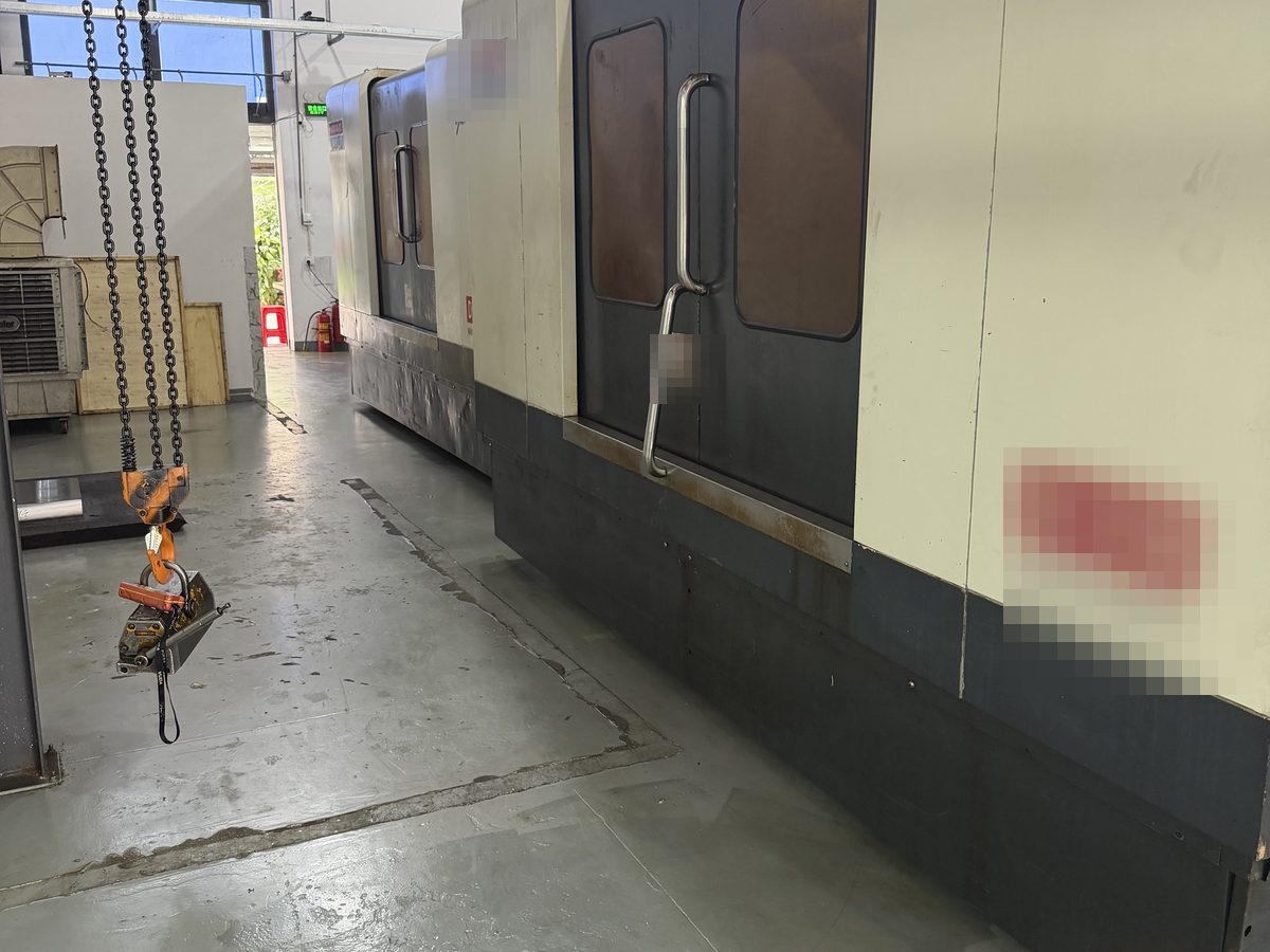
The water circuit is decided on the drawing, not at the machine. Plates get checked for flatness, pockets get measured, guide bores get gauged; the circuit is a set of holes inside the steel, so there is nothing to look at once the stack is assembled. It is also the feature that decides whether the tool hits its cycle — and unlike the cavity, which the mold maker finishes in his own shop, it is drilled here, in the base, before anything else arrives on the bench.
A circuit is a path through steel, not a pipe. There is no tube inside a mold base — just a sequence of straight drilled holes entering and leaving through the side and plate faces, meeting each other inside the steel. Water goes in at one port and out at another and follows the path of least resistance between them. The only reason it follows the route you planned is that every other opening is closed. One unsealed end turns a cooling circuit into a shortcut.
Only straight lines are available. A drilled channel can go wherever a tool can travel in a straight line from a face it can reach. The circuit has to live in the plate, around the pockets, the guide bores and the ejector pattern, without breaking into any of them. Deep pockets, tall cores and the narrow cores between cavities are the hard cases — not because the holes are long, but because the entry point has to be somewhere the tool can reach. Curved cooling that follows a sculpted surface is a different process, quoted as complex surface mold base work.
Depth is measured in diameters. In the trade a twist drill is comfortable to roughly four or five times its diameter before the flutes stop clearing chips and the hole wanders; through-tool coolant and a guidance bushing push it far beyond that. That is the difference between drilling a water line on a machining centre and drilling it on a deep-hole machine, which is why we run deep-hole drilling in-house. Depth also multiplies error: a small angular error at the entry becomes a large positional error at the far end, so on a long channel straightness matters more than the nominal port position.
Most of a cooling drawing does not need ±0.02 mm. A water line is not a fitting feature. Unless the drawing calls out something tighter it is held to our general non-fitting band of 0.3 mm, and what decides whether the circuit works is that the line stays inside the steel and the cross-drillings meet. Tightening every hole adds machine time and buys nothing. Keep the tight figures for the features that locate and seal — mold pockets, guide bores, shut-off faces — as set out in the tolerance note. If a channel truly has to be closer than that, say so, and it is quoted as the exception it is.
The distance to the cavity face decides the cycle. Put a channel too close and the wall of steel between them flexes under injection pressure: the part can show the line as a ghost ring, and a thin wall can crack during finishing. Put it too far away and the plastic cools slowly, the cycle stretches and the part warps. There is no universal number — it depends on the steel, the wall thickness and the pressure — so it belongs on your drawing. Cavity spacing sets how much room the circuit has to reach each station, which the pocket layout note covers.
Tall cores and crossings need more than a straight hole. Where two channels meet inside the steel, the second is normally drilled a little past the intersection so the two are certainly connected; that overshoot is a pocket of steel which cannot be left open, so it gets plugged. A straight line also cannot cool the middle of a tall core — that takes a baffle, a bubbler or a thermal pin, which means a port and space in the plate. If your design needs them, put it in the enquiry. An injection mold base is normally bought as the complete A/B assembly for exactly this reason: the pockets, the guide bores and the ports are made in one setup, in relationship with each other.
Plugs and ports are where customers lose a day. The ends of a circuit are closed with threaded plugs, and tapping costs nothing extra if it is on the drawing. The thread standard is the part that bites: BSP (G) ports are the norm across much of Asia, NPT is standard in North America, and a base tapped to one will not take the fittings of the other. Tell us which your plant runs before the ports are tapped. A plug is also only as good as the thread it sits in — over-tightening one in a thin plate strips it, and a stripped port leaks in a customer's press rather than in ours.
What a circuit looks like when it is wrong. You rarely see the fault on the bench; you see it in the press. One cavity running hotter than the others, a cycle longer than the simulation promised, a hot spot down one side of a part, or water arriving somewhere it should not be because an end was left open. Those symptoms point back at the four drawing decisions — position, depth, distance to the molding surface and the sealing of the ends — not at the drilling. We would rather ask two extra questions now than re-drill a finished plate.
Ask what the circuit will look like after two years. Scale and deposits close more circuits than drilling mistakes ever do, and the answer is mostly on the customer's side of the port: filtered, treated water, and a circuit that is not left sitting wet between runs. What can be written into the enquiry at this end is smaller but real — each line blown through with both ends open before the plates are wrapped, and the ports capped so nothing arrives already carrying swarf. Ask for it and it becomes part of the paperwork.
What to send with the enquiry. A circuit sketch with port positions and sizes; the thread standard your plant uses; the channel diameter; which plate each line lives in; the distance from the cavity face; any baffle or bubbler requirement; the plug type; and whether any line should be left open or capped. Add the plate list, the steel grades and the quantity and the job can be priced in one pass — the RFQ checklist covers the rest of the pack.
Where the circuit sits in our week. Water lines are drilled inside the same seven-day window as everything else, on our own deep-hole machines, alongside standard and custom bases, at 2,000+ sets a month. Minimum order is one set, and quotes go back against the drawing usually within one business day, on 50% deposit and 50% before shipment. Send the plate drawing with the circuit on it and we will tell you what the channels cost to drill — and where the geometry will not allow one.
Related