

Technical · 6 min read
Support pillars: breaking up the span under the core
Every plate in a mold base is bolted flat to the next one except the support plate. It spans, it bows under injection pressure, and the pillars under it are the only adjustment you get.
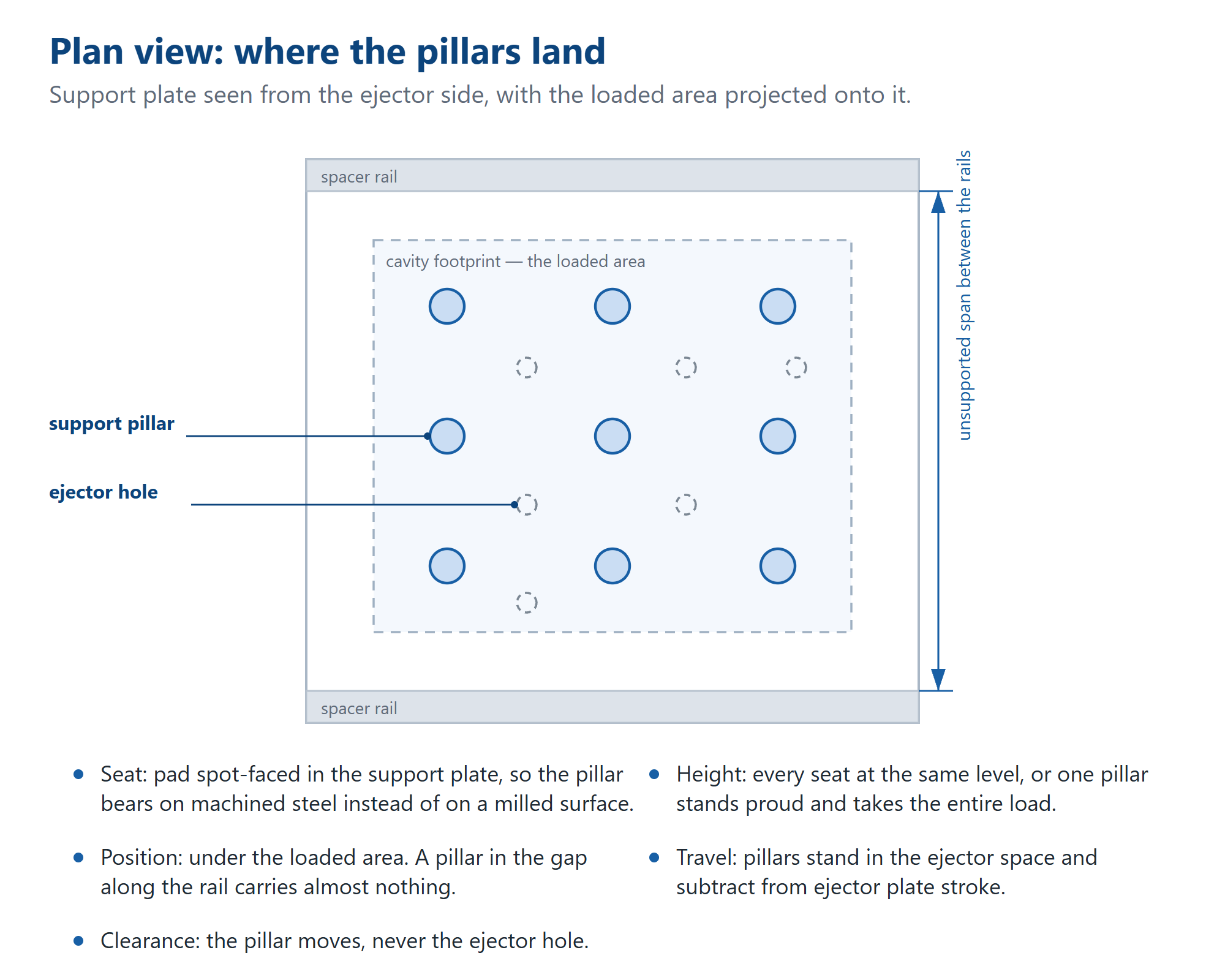
The support plate is the plainest plate in the stack: one slab, four edges, a field of ejector holes. It is also the plate that carries the core. On a large mold it rests on nothing at its centre — the spacer rails hold it along two edges and the ejector assembly works in the space underneath. Support pillars are how that span gets broken up. Where they land decides whether the core stays flat under injection pressure, and the symptom of getting it wrong never shows up on the base. It shows up on the part.
Follow the load. The clamp closes the tool and the melt pushes back. Pressure acting on the back of the core travels through the core insert into the support plate, then into the pillars and the rails, then the clamp plate and the platen. Every member in that chain is bolted flat against something larger — except one. The support plate is held at its edges and carries the middle of the core over open air. That is why a base which measures flat on the bench can still bow in the press, with nothing in an inspection record to show it.
What the bow does is small and uneven. The centre of the part flashes while the edges stay tight. Wall sections run thin in the middle and to size at the rim. In a multi-cavity tool the inner cavities short-shot while the outer ones fill. None of it reads as a base problem, so the gate gets moved, then the venting, then the clamp tonnage goes up — and the plate is never suspected, because nobody measures it under load.
There are only two ways to stiffen the arrangement: a thicker support plate, or a shorter span. Thickness is paid for once, in shut height, weight and price per plate — more large-plate machining, and more steel to lift. Pillars are paid for in the ejector space, which is already crowded and already dimensioned. Most drawings we see have chosen one of the two without saying so, and the choice is worth making on purpose: a deep ejector stack needs the room, a shallow one can carry the extra thickness.
Pillar layout starts from the loaded area, not from the space that happens to be left over. Project the cavity footprint onto the support plate — that rectangle is what has to be held. A grid across it, with extra pillars under deep ribs, hot spots and the land between cavities. The margin along the rails and the corners carry almost nothing, and pillars standing there are the mark of a layout that was worked around the ejection instead of around the load. On a custom base the pattern belongs on the drawing; on a standard frame it is usually a default.
What a pillar has to clear is a longer list than it looks: ejector holes, ejector plate travel, water lines, screw bosses, lifter seats, the knock-out hole. The rule that saves an argument later is simple — the pillar moves, never the hole. An ejector hole sits where the part needs pushing; shift it to make room for a pillar and the ejector force leaves the wall or the boss it was aimed at, and the part gets marked. A water line is worse, because moving it re-balances a circuit that was designed around the cavity. If a pillar genuinely has nowhere to go, the answer is a thicker plate — and that is a conversation for the drawing stage, not for the crate.
The seat matters as much as the pillar. A pillar standing on a milled surface beds on whatever happens to be highest. Spot-face the pad — one flat, square, machined seat per pillar in the support plate — and the pillar bears on steel that was cut to carry it. It is a short operation on a machine that is already set up, and it is the difference between a pillar that shares load and one that rocks on a high spot.
Then the heights. Three pillars of the same length, seated at the same depth, divide the load between them. One standing a hair proud takes all of it. That is worse than having no pillar at all: instead of a distributed support the plate gets a point load, the seat is dented, and a crack can start there and run to the nearest hole. The check costs nothing — stand the plate on a surface plate with the pillars in place and look for rock before it is packed.
So put it on the drawing: pillar diameter and whether it is shouldered, the seat diameter and depth, the positions — or the rule you used to place them — the clearance you need around ejection and cooling, and whether the pillars ship fitted or loose — they sit in our mold base components range either way, but the crate is packed differently. If the drawing only says “add support pillars”, what arrives is our default pattern, which is our reading of your load. On a standard frame that is harmless. On a large base with a hot centre it is not a decision to delegate.
What we do with it: seats machined at the stated positions and depth, pillars cut and checked to length, every seat verified on the same face before the plate leaves the machine. What we do not do is quietly redesign the load path. If the pattern looks thin for the footprint, it gets raised at quotation — when moving a pillar costs nothing but a line on a drawing.
The failures are recognisable once you know what to look for. Flash at the centre of the part with tight edges: span. A crack running from a seat toward an ejector hole: clearance, or a seat too shallow to spread the load. A polished ring on the top of a pillar and fretting dust under the plate: unequal height, one pillar doing the work. An ejector plate that will not complete its stroke: travel, the pillar is in the way. Each has a different fix, and none of them is more clamp tonnage.
If you are sending a base out to quote, send the pillar layout with it — or say that you want one proposed, and give us the cavity footprint and the ejector layout so the proposal means something. Most bases run 7–10 days from confirmed order to shipment, 2,000+ sets a month leave the shop, and the price comes direct from the factory floor rather than through a trading layer. A drawing and a footprint are enough to start.
Related