

Hole-making · 6 min read
Depth, not diameter: what a screw hole on a mold base has to get right
Diameter is on the drawing and everybody checks it. Depth is assumed — and depth is what decides whether a stack closes on its machined faces or comes to rest on its screw heads.
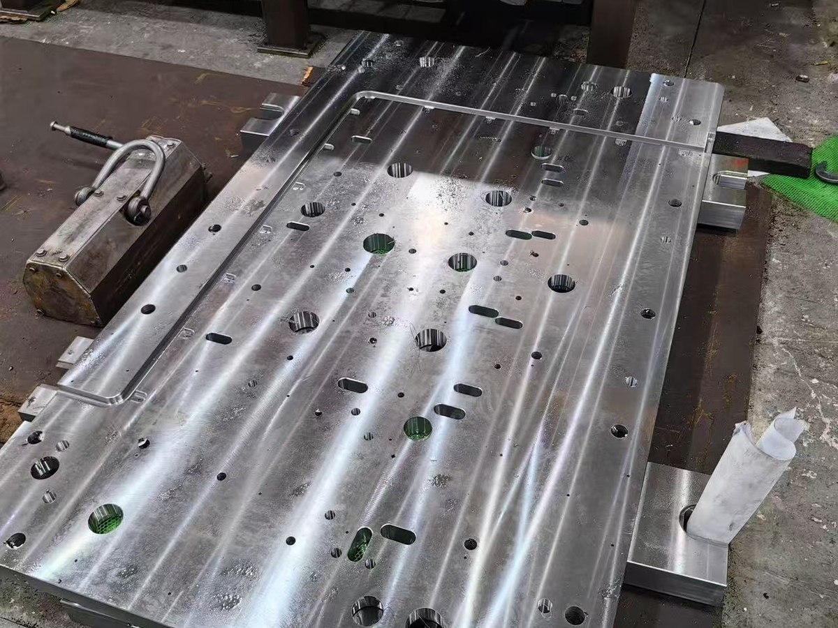
Every hole on a base plate arrives as a circle with a diameter, and the diameter gets the attention because it is visible. The circle says nothing about how deep the recess for the screw head goes, how far the thread runs, or how much steel is left under the bottom of the hole. On a plate carrying forty of them, those three numbers decide whether the stack closes on its faces or sits on its screw heads.
The seat carries the load, not the thread. A socket-head cap screw clamps nothing on its own. The clamp load is generated between the underside of its head and the thread it pulls against, and the surface in between — the counterbore floor — is what spreads that load into the plate. It is a machined face: flat, square to the screw axis, at the right height. A few hundredths high and the head stands proud, the plates close on the heads instead of on each other, and the symptom reads as a warped plate rather than a shallow counterbore.
Depth is a budget with three lines and one limit. Counterbore depth, thread length and the web of steel left under the thread all have to fit inside the plate thickness. A DIN 912 M10 screw carries a 10 mm head and sits in a counterbore roughly 11 mm deep; put a 30 mm thread under that in a 40 mm plate and the arithmetic is already negative before any web exists. One of the numbers has to change, and the earlier that happens the cheaper it is.
Four ways out when it does not close. Use a thicker plate — but that changes the closed height of the whole stack, so it has to be checked against press daylight and ejector stroke first, the same arithmetic three thicknesses of a plate forces on any order. Bolt through to a nut or a tapped plate behind, which the ejector housing often makes unreachable. Drop a fastener size, if the load allows it. Or move the hole, which is usually cheapest and the one nobody wants, because it moves a component.
The failure that survives inspection is the screw that bottoms out. If the tapped hole is shallower than the length of screw below the seat, the screw stops on the bottom of the hole with its head still above the counterbore floor. It tightens. It feels right. It holds nothing but its own tip, and the joint opens the moment the plate is lifted or warmed. Running the drill, boring bar and tap to a stated depth costs seconds; discovering the depth later costs a repair that cannot be done from the outside.
A counterbore off the thread axis is worse than a shallow one, because nothing about it looks wrong. The head lands on one edge, the preload goes in eccentric, and the joint still torques to the same felt tightness. It simply relaxes earlier. On a base that cycles between a cold shop and a warm tool, that relaxation appears as a stack which has moved a few hundredths and guide pillars that have lost the preload they were bored for.
Not every seat lands on a flat face. A cast back, a flame-cut edge, the wall of a pocket: cut a counterbore straight into one of those and the head sits on a single high point. Spot-facing first is the answer, and it is a different operation with a different purpose — a spot face is cut until it cleans up, not to a depth, which is exactly why it has to be called out separately on the drawing.
The web under the thread is a pressure boundary as well as a structural one. Too thin and the thread breaks out on the far face, or the plate bulges under preload. Thin it over a cooling line and the drill breaks into the circuit, so the thread then leaks along its helix. A weep of that kind does not show at assembly; it shows warm, in the press, a week before the run — the same reason a deep-hole cooling circuit is drilled from a known reference rather than “a bit deeper”.
Six lines settle it before anything is cut. The fastener standard and size (ISO 4762 M10, not “M10 screw”). The counterbore diameter and depth. The thread callout with its depth and whether it is through. Which face is the seat. Whether a counterbore may break into a pocket, a slot or another hole. And on a thin plate, the smallest web you will accept. Left to the title-block tolerance, a 30–120 mm dimension may move ±0.3 mm under ISO 2768-m — which is the entire clearance between a screw head and the face it is meant to sit below.
None of this is measured with a caliper. Seat depth goes on a depth micrometer or the CMM, the thread goes past a go/no-go gauge, and the seat is checked for squareness rather than mere presence. On a plate like the one above, the holes that cause trouble are the ones nobody measures: a hole two tenths shallow looks exactly like one that is right.
This is where a drawing hands a decision to the shop. Plenty of Chinese mold base suppliers quote precisely what the print says, and a print reading “M10 tapped” with no depth has said nothing about depth — the shop will pick a number that suits its tap. The fix is a line of text, not a negotiation. If you are still working out what buying a mold base from China involves, depth is a fair test question, because the answer shows whether anyone read the drawing.
We cut counterbores, tapped holes and slots in-house in Dongguan, China, on 20+ three-axis machining centres, holding fitting and ground faces to ±0.02 mm and ground surfaces at Ra 0.8 µm; plates over 600 mm are agreed piece by piece. A normal base order runs 7–10 days from confirmed drawing to shipment, the plant turns out 2,000+ sets and pieces a month, and you buy from the factory.
Related