

Technical · 6 min read
Slides and lifters: the space an undercut needs in your mold base
A part with an undercut cannot be moulded by a straight pull. Whatever solves it — a slide, a lifter, a split — has to live somewhere in the steel, and what gives it a home is the mold base.
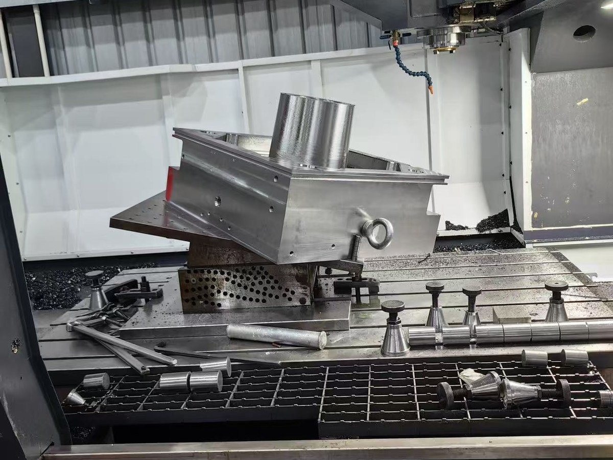
Most undercut parts arrive with the solution sketched: a slide on one side, a lifter under an internal rib, a split cavity. All three make the same request of the same place. A side action is invisible on the part print; on the mold base it is a pocket, a stop, a seat that has to be ground, and often a bore through two plates. Those are machined while the base is being made; a base cut without the room cannot be reasoned into having it afterwards.
The two answers work differently. A slide is a block of steel carrying a small piece of core: an angle pin drives it clear of the undercut as the mold opens, it travels past the undercut with margin, stops, and closes again on the way back. A lifter (angle ejector) is a blade standing on the ejector plate; as that plate rises, the blade moves up and sideways at once, releasing an internal undercut as it pushes the part off. What matters at the base is that each asks for a seat, travel, a stop and clearance — four machined features, not four lines on a print.
A slide does not rest in a rough pocket; it is guided. It runs between wear plates and guide strips, or in a pocket machined and ground to fit it, and those walls keep the core on the front of the slide in line with the cavity. The callout is the fitting-and-ground figure, ±0.02 mm, the same one that goes on a mold pocket or a guide-pillar bore (the guide bores); a clearance cut falls under the general 0.3 mm. Mark which pocket is a slide seat: quoted as a milled pocket, a fitting feature gets a clearance tolerance.
Travel and the stop are distances on the plate, not properties of the slide. The slide has to reach clear of the undercut with margin, so the gap between the cavity land and the outside edge is settled before the plate size is fixed. It also has to stop somewhere: a block bolted to the plate, or a face machined square into it. Both need room, and a machined stop face belongs with the ground faces. Ask how far the slide travels and what stops it; if the answer is the plate, that face is on the base drawing.
Something has to hold the slide closed. While plastic is going in, the pressure on the small core pushes the slide back out, and a wear plate or heel block takes that load. The surface it bears on is ground flat and square, so the force goes into the plate rather than into the angle pin. A guide slot at low load and a face carrying injection pressure every cycle are different jobs. Give the wear plate and guide strip thicknesses: pocket depth has to allow for them.
The room has to come from somewhere: everything above eats width, and a slide that has to clear an outer wall pushes the cavity inward, which either takes space from the cavity or grows the plate. On a standard size there is no spare; the arithmetic of a step up is in the note on standard sizes. A slide seat is one more claim on the same steel as the cooling circuit and the ejector pattern: a water line running through the space the slide must occupy is a leak waiting to happen or a line to move (cooling circuits), and an ejector pin rising inside the slide footprint pushes on the slide instead of the part (ejection). Both are cheap to settle at the layout stage, which is the argument in pocket layout: which features get the space, and which move.
A lifter is usually the cheaper answer, and its cost at the base is one hole. The blade rides in a bore through the core plate and the support plate beneath it, and it moves sideways because the bore is larger than the blade and its foot sits on the ejector plate. So the base owes you a through bore in two plates that lines up, clearance at the bottom for the blade to swing, and an ejector plate able to drive it. Two checks settle most of it: does the swing clearance clash with the ejector pattern, and does the bore pass where a support pillar or a screw already stands? Put it there and one of them has to move.
Nothing on a quotation is normally called slide. It appears as a pocket with ground walls instead of a milled clearance pocket; a square ground stop face; a ground seat for a wear plate; a through bore in two plates; and the layout work behind them. Two quotes for one part can differ simply because one supplier counted a pocket as a clearance cut and the other as a fitting feature — the difference described in reading a mold base quotation.
On many projects the base is ordered before the side action is settled, because the base sits on the critical path. So do not order the base tight and plan to add the pocket later: a seat cut after the plates have been ground means re-establishing the datum and working around finished faces. Two honest options: hold the layout and leave the pocket uncut with its position reserved, or settle the layout and order the base complete. “We will sort it out later” is the expensive one.
What to put on the drawing is a marked-up base view naming which pockets are slide seats and which are clearance; how far each slide travels and what stops it; the wear plate and guide strip thicknesses, so the pocket depth allows for them; each lifter's position, blade thickness, bore size and swing direction; the datum the layout is dimensioned from; and whether those features are machined now or reserved. Add the cooling and ejector layouts on the same sheet so the clashes can be checked before anything is cut — the list in what to send with a mold base RFQ, with the side-action items added.
Getting it wrong arrives at the press: a slide that drags and scores the part, an undercut dimension that wanders shot to shot because the seat is loose, an angle pin that shears because the load went through it instead of a heel block, a lifter that leaves a witness mark. All were decided while the base was still a drawing. Send the part print and the side-action layout with the plate list, and we will say which pockets are fitting features and where a lifter bore will clash — before the plates are cut. Bases carrying slide seats and lifter bores come through as custom and non-standard work and as part of an injection mold base: the seven-day figure applies to the standard sizes and the plain jobs, over 2,000 sets and pieces a month run through our own floor so a layout that needs extra seats does not wait for a convenient batch, and there is no middleman between your drawing and the machine that cuts it.
Related