

Technical · 6 min read
Parting-line vents: what the mold base drawing must show
Air needs a route out of the cavity before the melt arrives. That route crosses a sealing land, a relief channel and the plate edge — and each part belongs to a clear machining scope.
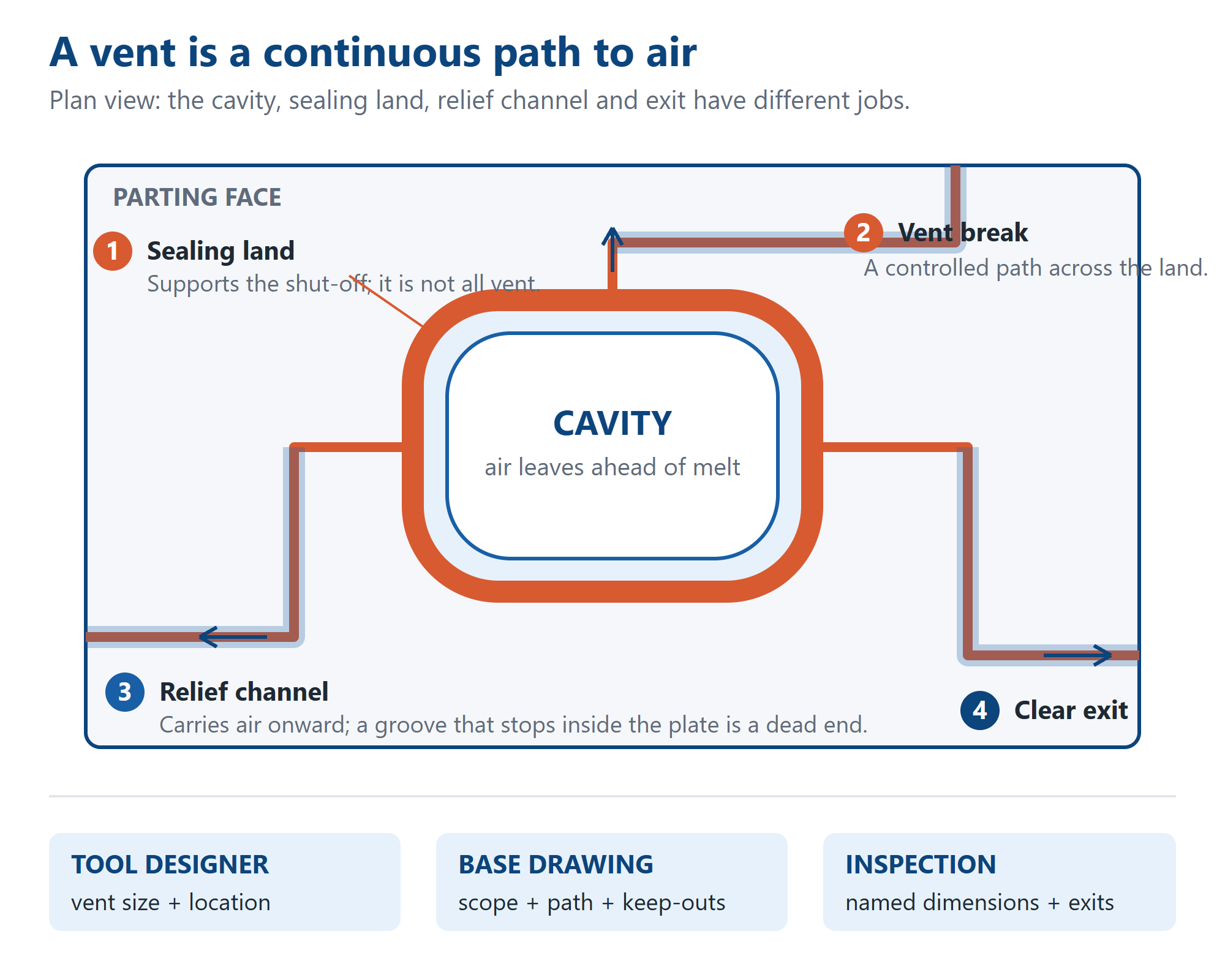
A mold cavity is full of air before every shot. As the melt advances, that air has to leave without lifting the parting line or becoming trapped at the last place to fill. Parting-line vents provide one controlled escape route. Yet an injection mold base quotation often describes plates, pockets and guide bores in detail while venting is reduced to “standard”. That is not enough information for a shop to cut from, because the useful feature is a path through several zones, not an isolated slot.
Three zones do three different jobs. The sealing land is the parting-face area that supports shut-off around the cavity. A vent break is the deliberately shallow path across that land, sized by the tool designer for the resin and the tool. Beyond it, a relief channel carries the escaping air onward with less restriction. The land must still support contact; the vent break must let air through without inviting flash; the relief must not become the new bottleneck. Treating the whole parting face as a vent sacrifices the first job rather than improving the other two.
A groove that stops inside the plate is a dead end. Trace the route on the drawing from the cavity to a free edge or to a deliberately designed collection or vacuum connection. Then look at what occupies the route: a clamping face, a spacer rail, a screw boss or another plate may close it when the tool is assembled. An attractive channel on an individual plate can therefore do nothing in the stack. The exit side belongs on the base drawing, together with the assembled keep-outs. This is layout work in the same sense as the cavity, guide and hardware competition described in pocket layout.
There is no responsible universal vent depth to paste onto every order. The workable geometry depends on the material, the molding process, the cavity and the sealing design. Too little effective path can contribute to trapped air, short shots or burning; too much opening at the sealing boundary can permit flash or weaken the local contact. The mold designer should name the vent locations and dimensions. The base maker should machine the specified features and flag a broken path, rather than silently substituting a house number.
The base-versus-insert boundary has to be explicit. If cavity inserts will be finished in your toolroom, their local vent geometry normally belongs with that insert work. The frame order may still need relief channels, exits and clearance through neighbouring plates. Those features must meet the insert design without cutting across a precision pocket seat or leaving an unplanned step in the air path. A combined frame-and-insert order can coordinate the whole route in one package; a split order needs an interface drawing. The commercial boundary is the same one described in where the frame ends and the inserts begin.
Vent paths also compete with services already inside the base. A cooling channel crossing a relief groove is not two valid features in the same place; it is a potential leak and a blocked air route. Ejector pins, return pins, screws, support pillars and slide seats can interrupt the path just as effectively. Ask for one overlay that shows vents alongside water and hardware before machining. The need for that combined view is familiar from cooling-channel layout: the feature that arrives last should not be the one that discovers every clash.
Finishing can preserve a vent or quietly close it. A shallow feature is easy to lose through uncontrolled stoning, edge rounding or a burr raised while machining an exit. The sealing land also has to remain a supported face rather than being relieved by accident. The drawing should therefore distinguish contact, vent and relief areas instead of relying on colour alone, and the machining sequence should protect the functional edges. If your own toolroom will complete final fitting, state the stock and the unfinished operations expected on arrival. “Ready for assembly” and “ready for our venting work” are different deliveries on a custom mold base.
A curved or stepped parting line makes the same problem three-dimensional. Air still needs a continuous route, but the sealing band changes height and a plan-view groove may not describe where it crosses the surface. Mark the contact band, vent breaks and relief regions on the model as well as the controlling drawing, and identify the datums used to inspect them. This sits directly beside the contact-versus-relief decision in curved parting lines. A smooth model without those boundaries leaves the machine operator to guess which surface was meant to seal.
Inspection should test the drawing's intent, not merely report that grooves exist. For vent features inside our machining scope, agree which locations, widths, depths and land dimensions need recorded values, and check that the relief reaches the intended exit. A visual path check and a dimensional report answer different questions; neither replaces the other. Our standing inspection practice is that work is checked before dispatch and records travel with the shipment, but a useful record starts with named features. The broader document boundary is set out on our quality page. We would not claim a universal measuring method for every vent geometry; the inspection plan follows the feature.
For buyers sourcing from China, this is primarily a file-preparation issue. A Chinese mold base supplier cannot infer the correct vent depth from a photograph of the part, and should not invent it to keep the quotation moving. Send the resin and process information to your tool designer, then send us the controlled vent layout, the base/insert scope, the exit faces and the hardware and cooling overlays. That is a specific example of what buying a mold base from China actually involves: distance is manageable when design ownership and machining instructions travel in the same package. Our shop in Dongguan, China can then quote the cuts that are actually required.
A practical RFQ therefore needs seven answers: which faces seal; where each vent break is; the designer's dimensions for those breaks; where the relief channels run; which external faces must remain clear; which features belong to the base and which to the inserts; and what final fitting or venting your own shop will perform. Include the model revision and identify any no-go areas created by water, ejection or clamping. The general package in what to send with a mold base RFQ covers the plate list, steel and tolerances; add this vent map so the quotation does not hide a second design decision behind the word “standard”.
The buying value is straightforward: a defined air path prevents both an underspecified base and an overbroad machining allowance. Ordinary bases usually ship from our Dongguan, China plant in 7–10 days; non-standard vent layouts and insert interfaces are reviewed against the drawing and given a firm date before cutting. Capacity is 2,000+ sets and pieces per month, and you deal directly with the factory machining the plates. Send the vent layout with the base drawing, and the first discussion can be about path continuity, scope and inspection rather than a surprise after the inserts arrive.
Related