

Technical · 6 min read
A square through-opening is not a milled pocket
A window that goes right through a plate has no floor and no perfectly sharp corners. What the drawing must settle before a wire-cut EDM job is programmed.
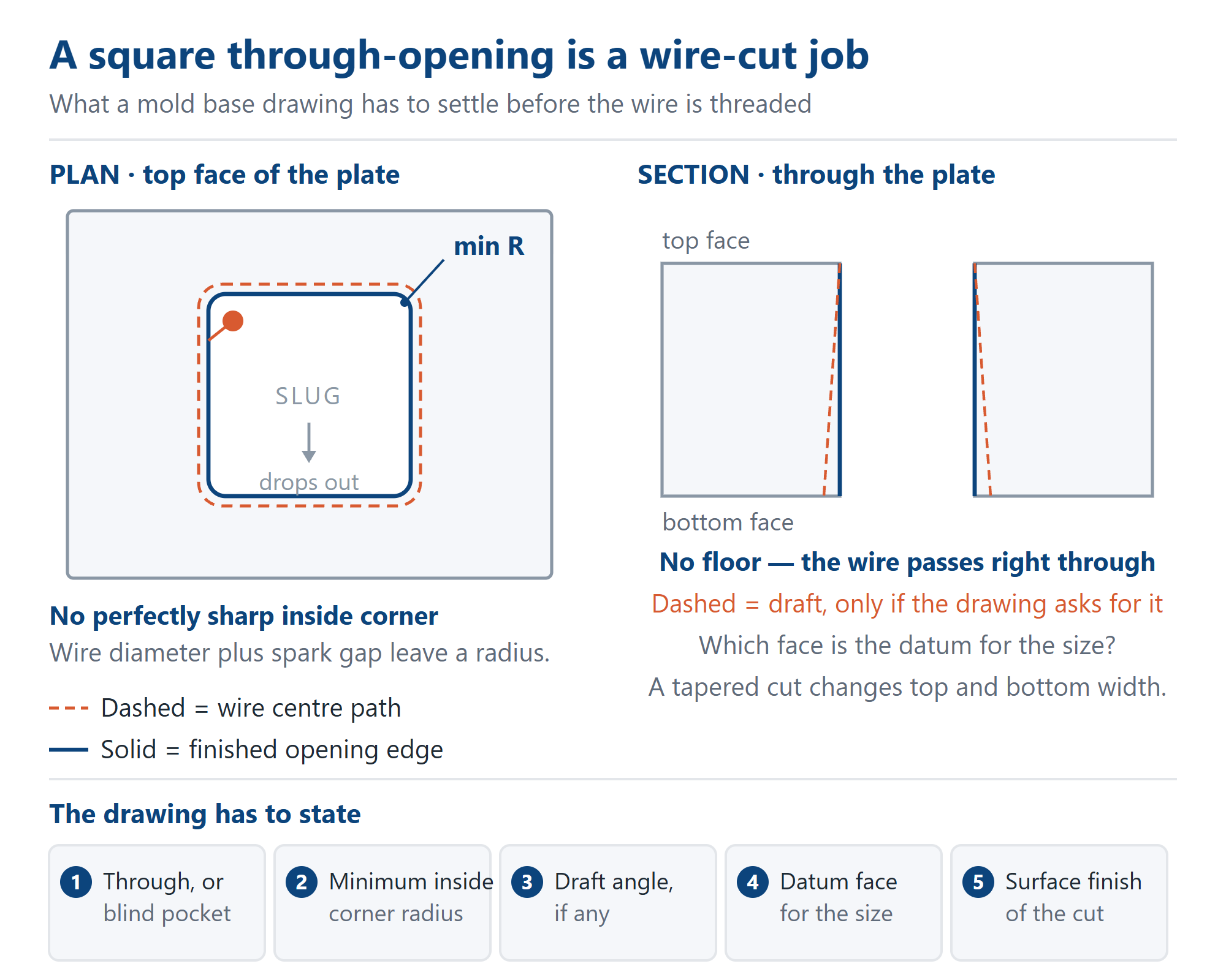
Most features on a mold base drawing are milled: a rotating cutter leaves a floor and its own radius in every inside corner. A rectangular window that goes right through the plate — for a slide, a lifter or an insert pocket — is not one of them. It has no floor, and if its corners are called square, a rotating cutter cannot finish them at all. The process is wire-cut EDM, and the drawing has to carry decisions a milled pocket never needs.
Through or blind picks the machine. A wire must pass through the plate, entering one face and leaving the other, so wire-cut EDM is the natural route for a window, a slot or any aperture with no bottom. A blind pocket with square inside corners is a different job: as the note on inside radius and tool reach explains, a milling cutter leaves its own radius, so a square blind corner needs an EDM (die-sinking) electrode or a design change. Write “through” or give a floor thickness; do not leave the shop to infer it from an undimensioned section.
An internal opening needs a way in. The wire is threaded through a small start hole drilled in the slug — the scrap that will be cut out — then follows the contour. An open-sided slot entered from the plate edge needs no start hole. It is easily omitted from a 2D drawing because it is not a finished feature, yet its position decides where the cut begins and ends, and the closing point leaves a witness on the edge. If that edge will seal or guide something, say which face may carry it.
No wire-cut corner is perfectly sharp. The wire has a diameter and the discharge removes a little more material around it, so every inside corner comes out with a radius the program cannot make smaller. Calling R0 asks for something the process does not produce. State the largest inside radius the mating part will accept, or ask for the smallest the shop will hold on that plate thickness. That is the same interface-versus-free-area discipline as a second complete base: only corners registering with a component need a tight callout.
The wire centre path is not the finished edge. The program offsets the path by the kerf so the cut leaves the dimension on the part, and the piece inside drops away as a slug. Which side is the part and which is scrap must be unambiguous, especially on a narrow web between two openings: a mirrored profile or a reversed offset does not show up until the slug is out, and by then the steel is gone. A section dimensioned on the web itself, and a note on how the slug is retained until the cut closes, remove the guesswork.
Wire can be tilted, so draft needs a datum face. A vertical wire gives walls square to the plate faces; a tilted wire cuts draft, useful when an insert has to seat into or release from a window. Draft needs an angle and one more thing: which face carries the nominal size, top or bottom. Without that, a tapered cut is correct at one face and something else at the other, and both readings can be defended. Name the datum face on the print — the clamping datum note covers why it matters elsewhere too.
An as-cut wire edge is not a milled or ground surface. The discharge leaves a thin altered layer, and a first pass is not the finish a sliding component should run against. Where the opening guides a slide or a lifter, specify the required finish and whether finish passes are expected, not just “wire cut”. Where nothing touches the window, an as-cut edge is adequate and specifying more buys nothing.
Position is a fit question, not a general-tolerance question. An opening that registers with an insert, a slide body or the mating half must be located from a named datum — an edge, a bore or the guide-pillar centres — and given its own size and position callout. Our own callout for fitting and ground faces is ±0.02 mm, with ground faces at Ra 0.8 µm; both are our figures, not a general-standard claim. Non-fitting features sit inside a general 0.3 mm band. A window declared neither fit nor clearance belongs to neither group, which is how two correct measurements disagree.
Ask for measured values at both faces. A through-opening can be right at the top and slightly different at the bottom if the wire was not square to the plate, and a report saying only “OK” describes a decision, not a size. What an inspection record proves makes the point generally: what matters is the measured number, its datum and the state it was measured in. For a wire-cut window add wall squareness and the corner radius, and name the measured face. Those values are what a replacement insert will be made to years later.
For buyers sourcing a mold base from China, the drawing carries more weight. A toolmaker down the road can settle “through or blind” at the machine; a Chinese mold base supplier working from an emailed file has to find the answer in the file. Distance does not change the geometry — it changes the cost of one unanswered question: a round of email, sometimes a plate remade. Send a 2D drawing with the through callout, minimum inside radius, draft and datum face, finish and start-hole region alongside the 3D model. That is one practical part of what buying a mold base from China actually involves: the controlling information travels with the order. Chinese mold base suppliers can quote such an opening from that set; none can do it from an unlabelled hole in a model.
Then expect the method to be named in the reply. A quotation saying “openings machined” without stating whether a window is milled, wire-cut or burned with an electrode has left the largest process variable unstated — and that variable is part of the date. Wire-cut EDM is a second setup on a different machine; there is no shaped electrode to make, but the job still needs a slot in the queue. Reading a mold base quotation sets out the rest; here, ask for the method and the datum the opening will be measured against.
A workable drawing therefore settles six things: through or blind; the minimum inside corner radius; which side of the contour is the part; the draft angle and the datum face carrying the nominal size; the finish on the cut edge; and the datum the opening is positioned from. Add a section through the web and a request for measured values at both faces. Ordinary mold bases from our Dongguan, China mold base lines usually ship in 7–10 days; capacity is 2,000+ sets and pieces per month; and you deal directly with the factory that will cut the opening, so the drawing and the wire are in the same place. If the window is for a slide or a lifter, our custom non-standard mold base line is where that conversation starts.
Related