

Product / case · 6 min read
A three-plate mold base has to open in the right order
Pin-point gates need a floating runner plate. That plate adds opening planes, travel limits and press stroke to the drawing — and a runner that has to fall clear on its own.
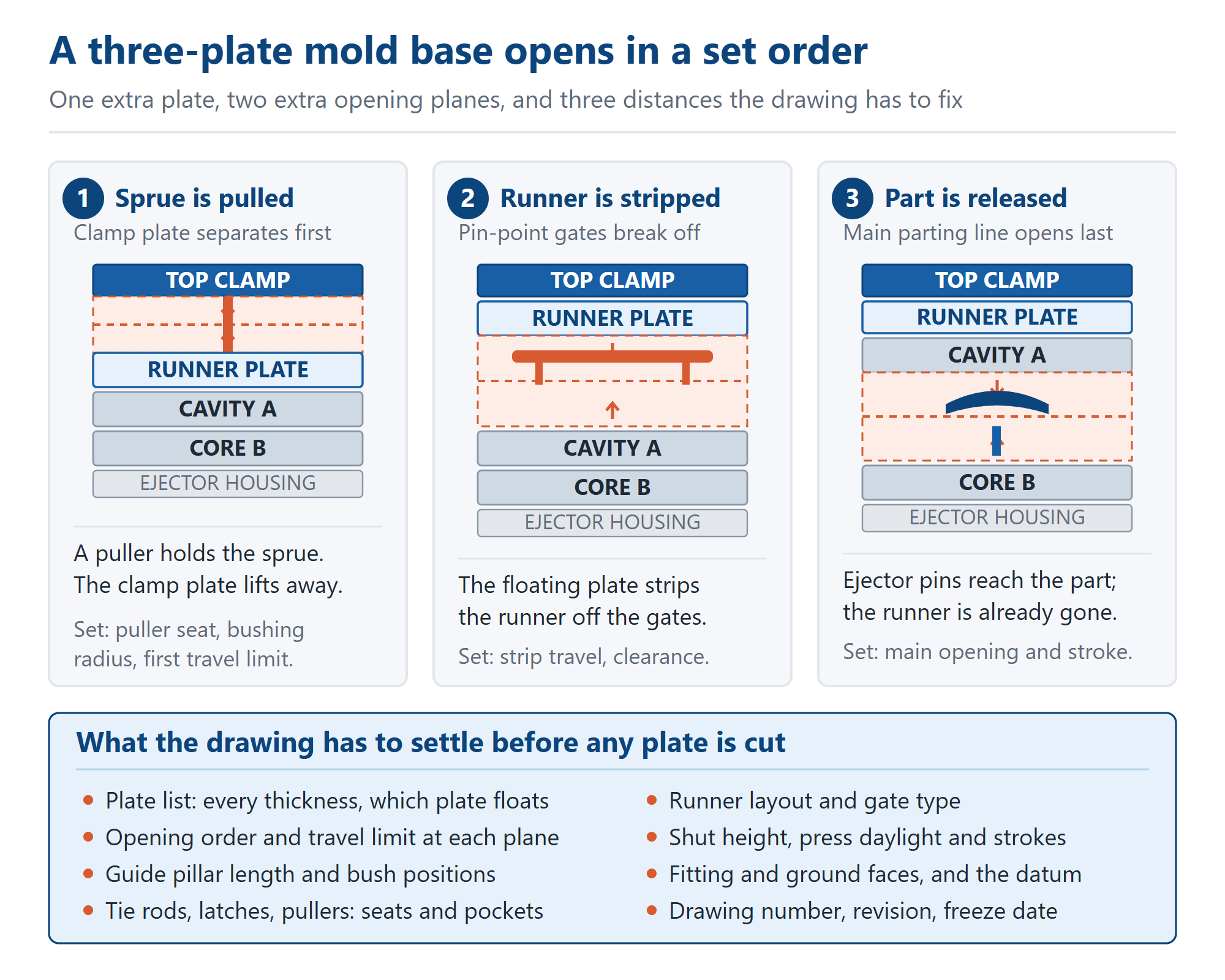
A two-plate mold base has one opening that matters: the A and B plates part, the ejector pushes the part off the core, and the runner goes with it. A three-plate base adds a floating runner plate between the top clamp plate and the cavity plate so pin-point gates can feed from above. That extra plate turns one opening into a sequence. Which plane opens first, how far each travels, and what holds the sprue until its turn are drawing decisions, not choices a shop makes at the machine.
The third plate exists for the gate. An edge gate sits on the main parting line and leaves a witness on the rim; a pin-point gate enters through the top face of the cavity, often near its centre, and breaks off when the runner is pulled away. That suits cosmetic parts and balanced multi-cavity feeds. The runner therefore has its own plane between the runner plate and the cavity plate, with a short tapered gate into each cavity. No ejector pins sit behind it — plate movement removes it, so the drawing must set that movement in order.
Three separations, three distances. First the top clamp plate leaves the runner plate and a sprue puller drags the sprue out of the bushing. Then the runner plate leaves the cavity plate, pushing the runner off the pin-point gates so it falls clear. Only then does the main parting line open and the ejector release the part. Each is a travel limit, not a direction: too little leaves the sprue seated; too far runs out of leader-pin engagement or press stroke. Put a number, a datum and an order against all three. A print saying only “three-plate” leaves the mechanism to be invented at assembly.
The order is held by hardware, not by the press. Tie rods or limit bolts set how far the floating plate travels, latches hold one plane shut until another opens, and springs or stop pins set which plate moves first. The mold designer usually specifies those parts; the seats, clearance pockets, tapped holes and counterbores are machined into our plates. Write down who supplies the hardware, who owns its dimensions and which holes we cut. One mold base, three parties sets out why a drawing with three owners needs one named revision.
Start with the plate list. Name every plate, give its thickness, say which one floats, and mark the datum the stack is measured from. The runner plate adds shut height, and every bore above it moves with that number. Give the steel grade per plate rather than one grade for the whole stack — P20, 718 or 738 covers why a structural plate and a cavity plate are bought for different reasons. Where a thickness is nominal, name the face that carries the finished dimension.
Guide pillars have to reach further. The floating plate rides on leader pins through its whole stroke, so the pins must stay engaged at full open, and the bushes in the runner plate must be bored to the same datum as those in the cavity and core plates. Size the pillars for the closed stack only and the plate can cock at the end of its travel — one gate breaks before the others and the runner hangs on the rest. Guide pillars and bushes explains why the bores decide how the tool runs.
The press has to fit the whole envelope. The runner plate adds shut height, and three openings need more opening stroke than a two-plate tool of the same part. Check tie-bar spacing, minimum and maximum mold height, daylight, clamp stroke and the ejector coupling before the plate list is frozen. Where the base meets the press lists the five interfaces a drawing has to name; add the total opening stroke and the space for the runner to drop. A tool that cannot open far enough to release the runner is a plate list approved too early.
Ejection belongs to the moving half. The ejector pattern, return pins, support pillars and knock-out coupling are laid out from the core side. The runner has no part in that pattern: it must fall free of the fixed half, with no clamp, ledge, hose or connector in the chute. Ejector pin holes explains why that pattern is decided last. On a three-plate base the two systems are independent, and the drawing should say so.
Services have less room. Cooling circuits normally run in the cavity and core plates; the runner plate above them usually carries no water, but it does carry the runner, the puller and the tie-rod pockets. Ports, O-ring seats and connector positions therefore have to be fixed before the gate positions are final. Circuits drilled from two datums meet with a step unless both halves share one reference, as deep-hole drilling of a cooling circuit describes. Put both schedules on one drawing.
Two decisions are the buyer's. The gate land and its length set how much witness the moulded part carries; say what is acceptable at the gate position, because a clean break and a flush surface are different requirements. The shut-off faces on both sides of the runner plate are fitting faces, so ask for measured values with datum, face and revision beside each number, not a pass tick — what an inspection record proves sets out why. Our own callout for fitting and ground faces is ±0.02 mm and Ra 0.8 µm on ground faces; those are our figures, not a claim of compliance with a general standard.
For buyers sourcing a mold base from China, the sequence is what gets lost between the design office and the machine. A local toolmaker can adjust a latch at the press; an order placed with Chinese mold base suppliers has only the drawing. Send the opening order, the three travel limits, the hardware list and the press envelope with the plate list, and ask for the sequence to be confirmed in the quotation reply. Our shop in Dongguan, China works that way — one practical part of what buying a mold base from China actually involves.
Seven lines settle most three-plate enquiries.
1. The plate list: every thickness, steel per plate, which plate floats.
2. Opening order and a travel limit for each plane.
3. Who supplies latches, pullers and tie rods, and the seats we cut for them.
4. Leader-pin length and bush positions.
5. Gate type, land, acceptable witness, runner and port schedules.
6. Shut height, daylight, clamp and opening stroke, ejector coupling.
7. Datum, functional faces, drawing number and revision letter. What to send with an RFQ covers the rest.
A three-plate base is normal work here: pin-point gate and three-plate systems belong to the standard plastic mold base line, and the same plate list applies to an injection mold base or a custom non-standard base. Ordinary mold bases from our Dongguan, China mold base lines usually ship in 7–10 days; capacity is 2,000+ sets and pieces per month; and you deal directly with the factory that bored the plates. Send the drawing with the opening sequence marked and we will confirm what the runner plate needs.
Related